
Propeller strut device of floating crane

A floating crane and herringbone technology, applied in cranes and other directions, can solve problems such as the inability of the herringbone to meet the navigable conditions of bridges, the inability to meet the requirements of bridge navigable height limits, and the reduction of the navigable height of the whole machine, so as to avoid capital and The effect of labor cost, simple and practical structure and low cost

Inactive Publication Date: 2013-04-03
DALIAN HUARUI HEAVY IND GRP CO LTD
View PDF3 Cites 4 Cited by
  • Summary
  • Abstract
  • Description
  • Claims
  • Application Information

AI Technical Summary

Problems solved by technology

The front struts, rear pull rods, and jibs of the gable frame are all installed on the crane turntable. When the floating crane is navigating along the coast or inland rivers, the commonly used crane jibs can be placed on the shelving frame of the hull or on the deck to meet the requirements of navigation. height, once the gable frame is super high, it cannot meet the navigation height limit requirements of some bridges
The herringbone frame of the large floating crane bears the load and has a large external dimension, and the connection between the front strut, the rear tie rod and the turntable is usually welded or hinged; Therefore, the whole process is complex, labor-intensive, time-consuming and labor-intensive, and the work efficiency is extremely low; and the repeated disassembly and installation of large structural parts will make it difficult to guarantee the performance of the equipment , leaving security risks
Although the above-mentioned large-scale floating crane can reduce the elevation angle of the jib in the non-working state, the elevation angle of the jib can be reduced to 0° under normal conditions to reduce the navigable height of the whole machine; however, due to its own herringbone The bridge's navigable conditions cannot be realized even if it is super high

Method used


Image

  • Propeller strut device of floating crane
  • Propeller strut device of floating crane
  • Propeller strut device of floating crane

Examples


Embodiment Construction

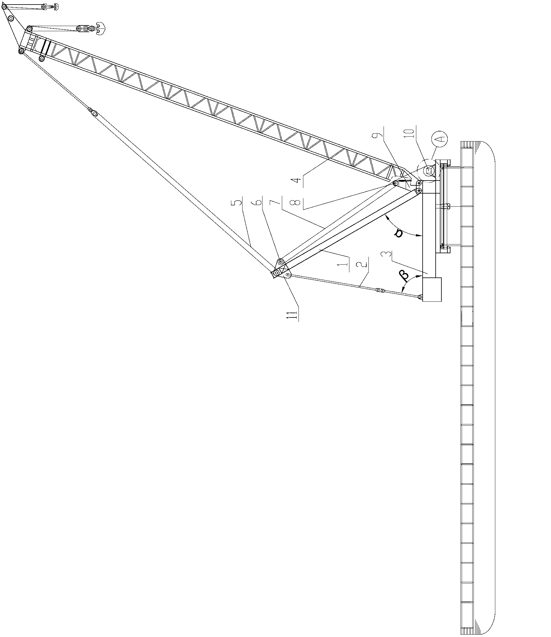
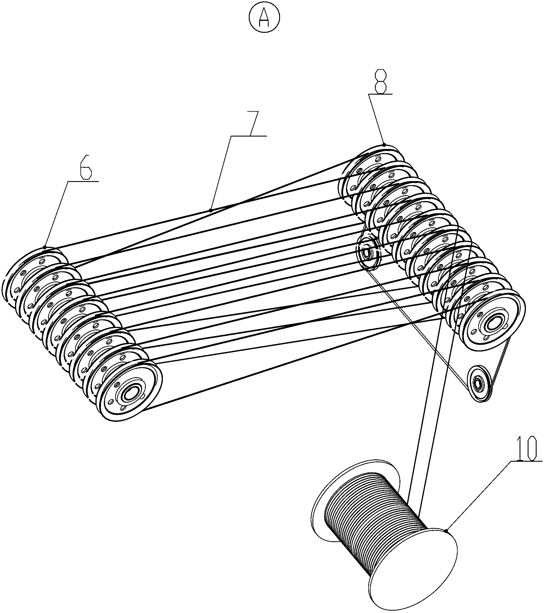
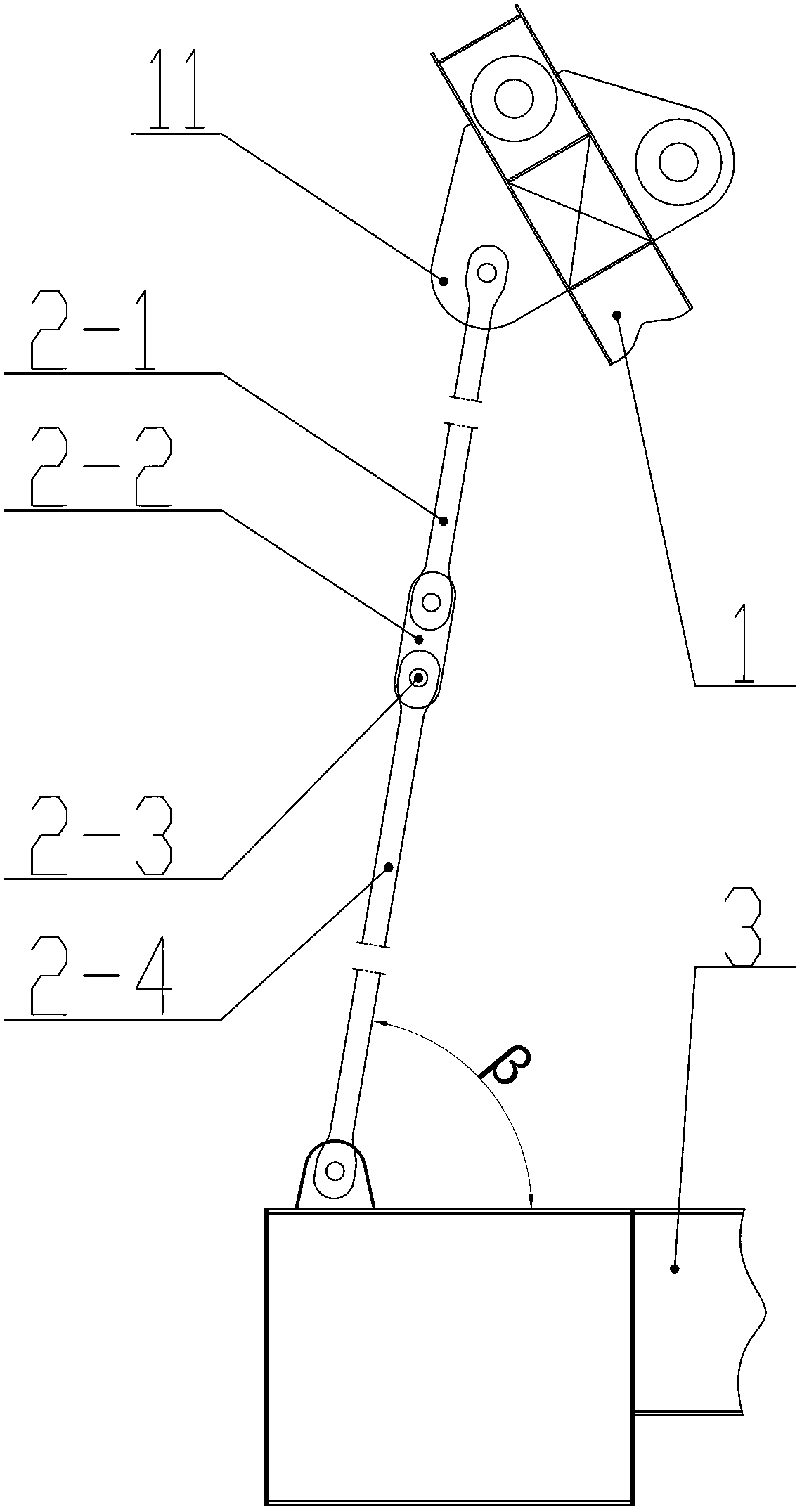
[0021] figure 1 Shown specific embodiment of the present invention, it is according to the large-scale floating crane crane that needs " its navigable state deck upper limit is high 14m requirement " according to the design, the herringbone device of the floating crane installed; Its structure comprises front strut 1. The foldable rear tie rod 2 and the turntable 3 are characterized in that: the herringbone frame adopts a folding type herringbone frame, and the foldable type herringbone frame is hinged at one end of the turntable 3 and the bottom end of the foldable rear tie rod 2 , the foldable rear tie rod 2 is composed of a first pull plate 2-1, a connecting frame 2-2, a pin shaft 2-3 and a second pull plate 2-4, and the top of the foldable rear pull rod 2 is hinged on the connecting plate 11, the angle between the foldable rear pull rod 2 and the turntable 3 is β angle; the other end of the turntable 3 is equipped with a support 9, a movable pulley block 6, a steel wire r...


PUM


Abstract

The invention relates to a propeller strut device of a floating crane of a large floating crane. The propeller strut device of the floating crane is characterized in that one end of a turntable is hinged with the bottom end of a folding rear draw bar composed of an A pulling plate, a connecting rack, a pin shaft and a B pulling plate; the top end of the folding rear draw bar is hinged with a connecting plate; the included angle of the folding rear draw bar and the turntable is beta; a propeller strut retracting device composed of a bracket, a movable pulley block, a wire rope, a fixed pulley block and a winding mechanism is assembled at the other end of the turntable; and located falling and located ascending of the folded propeller strut are achieved by contracting and winding of the wire rope by the winding mechanism. The propeller strut device not only has reasonable design, and simple and practical structure, but also can put down and lift the propeller strut in the manners of folding the propeller strut rear draw bar and winding the wire rope together with the winding mechanism, achieves clear and smooth navigation of the large floating crane in coastal water or inland river, and has the characteristics that the propeller strut device is high in efficiency, simple to operate, convenient to maintain, small in investment, low in cost, safe to operate, convenient to use, and the like.

Description

technical field [0001] The invention belongs to crane equipment and relates to a gable device of a floating crane. Especially suitable for large floating cranes. Background technique [0002] As we all know, its floating crane is the key equipment mainly used for offshore or inland river installation, salvage and river dredging. At present, with the forward development of economy and science and technology, the models of its floating cranes are also getting bigger and bigger. For example, the large floating cranes that appear on the market cannot pass through the bridges that have been built on the coast and inland rivers due to the high girder frame, and cannot navigate smoothly to the construction site. Its commonly used floating crane herringbone frame structure (attached Figure 5 ), its main structure includes front struts, rear tie rods, jibs and turntables, the bottoms of the front struts and rear tie rods are hinged or welded on the turntable, and the tops of the t...

Claims


Application Information

Patent Timeline
IPC IPC(8): B66C23/78B66C23/64
Inventor 籍波郭春晓
Owner DALIAN HUARUI HEAVY IND GRP CO LTD
Learn More