
Monofilament tension control mechanism

A tension control mechanism and monofilament technology, which is applied in the direction of conveying filamentous materials, thin material processing, transportation and packaging, etc., can solve the problems that monofilaments cannot automatically realize real-time tension adjustment, so as to improve reliability and stability, Avoid the use of electrical components and ensure the effect of product quality

Active Publication Date: 2013-04-03
FUJIAN SBS ZIPPER SCI & TECH CO LTD
View PDF5 Cites 2 Cited by
  • Summary
  • Abstract
  • Description
  • Claims
  • Application Information

AI Technical Summary

Problems solved by technology

[0004] The invention provides a monofilament tension control mechanism, the main purpose of which is to overcome the problem that the monofilament cannot be automatically adjusted in real time during the conveying process

Method used

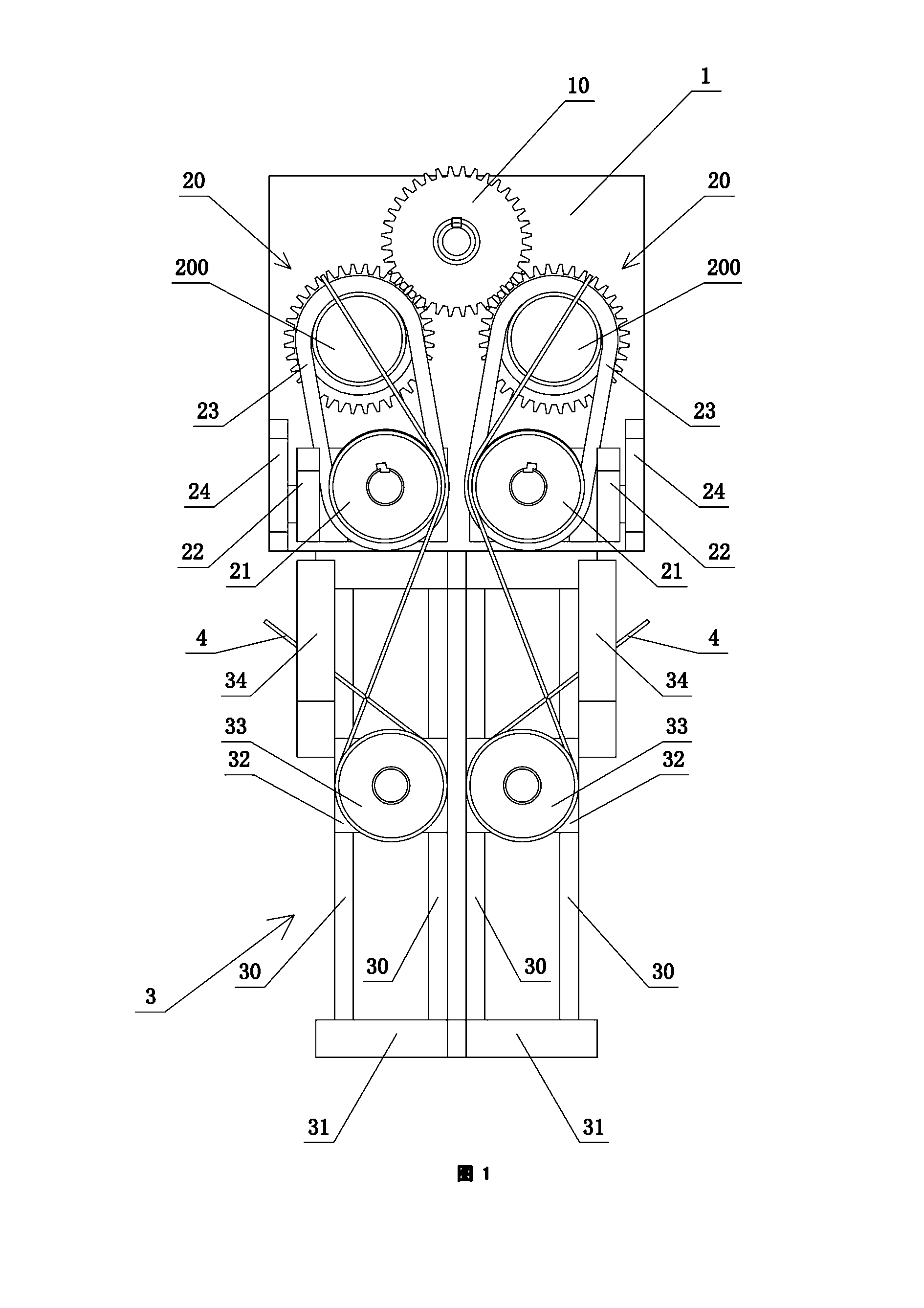
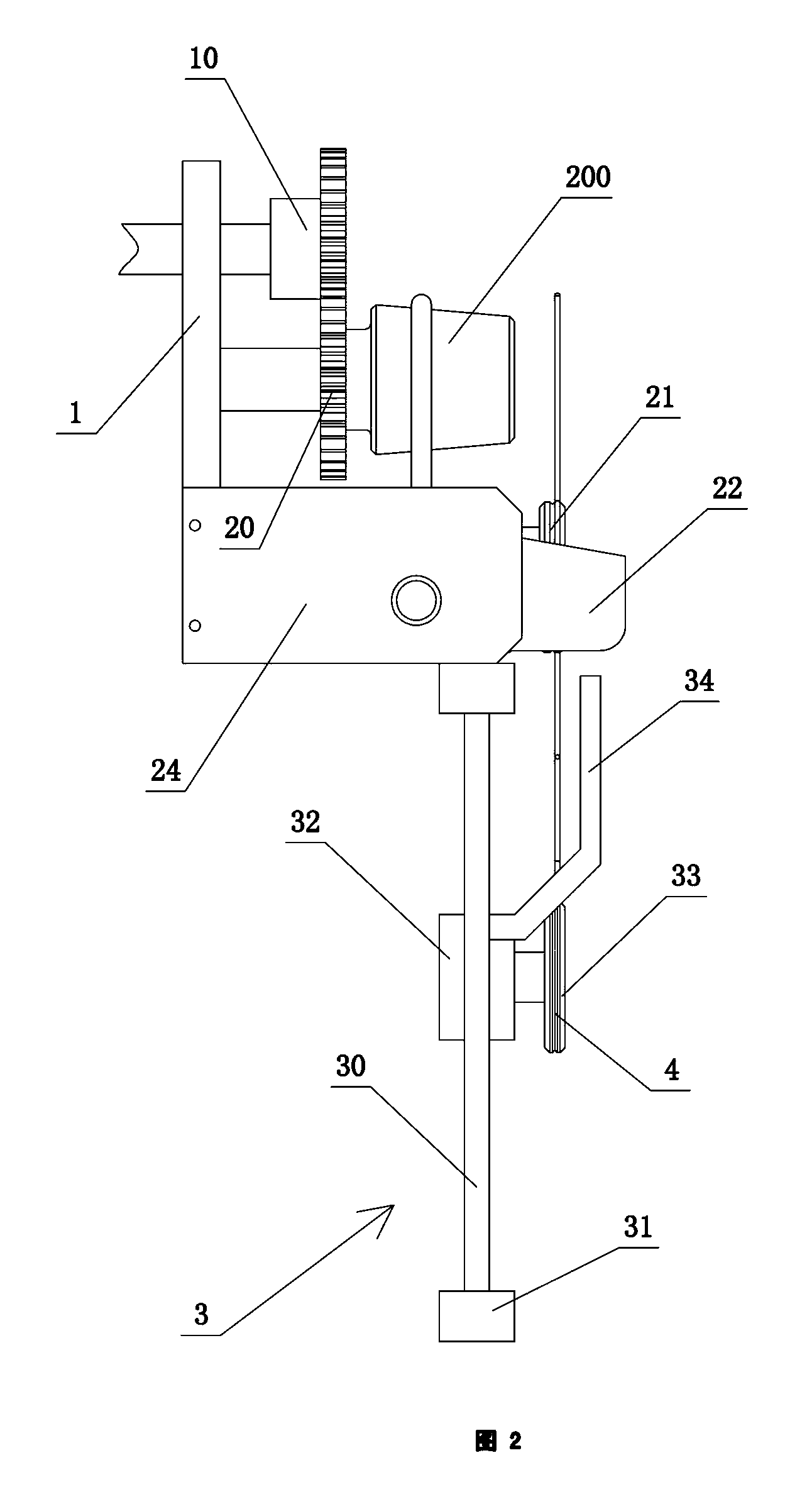
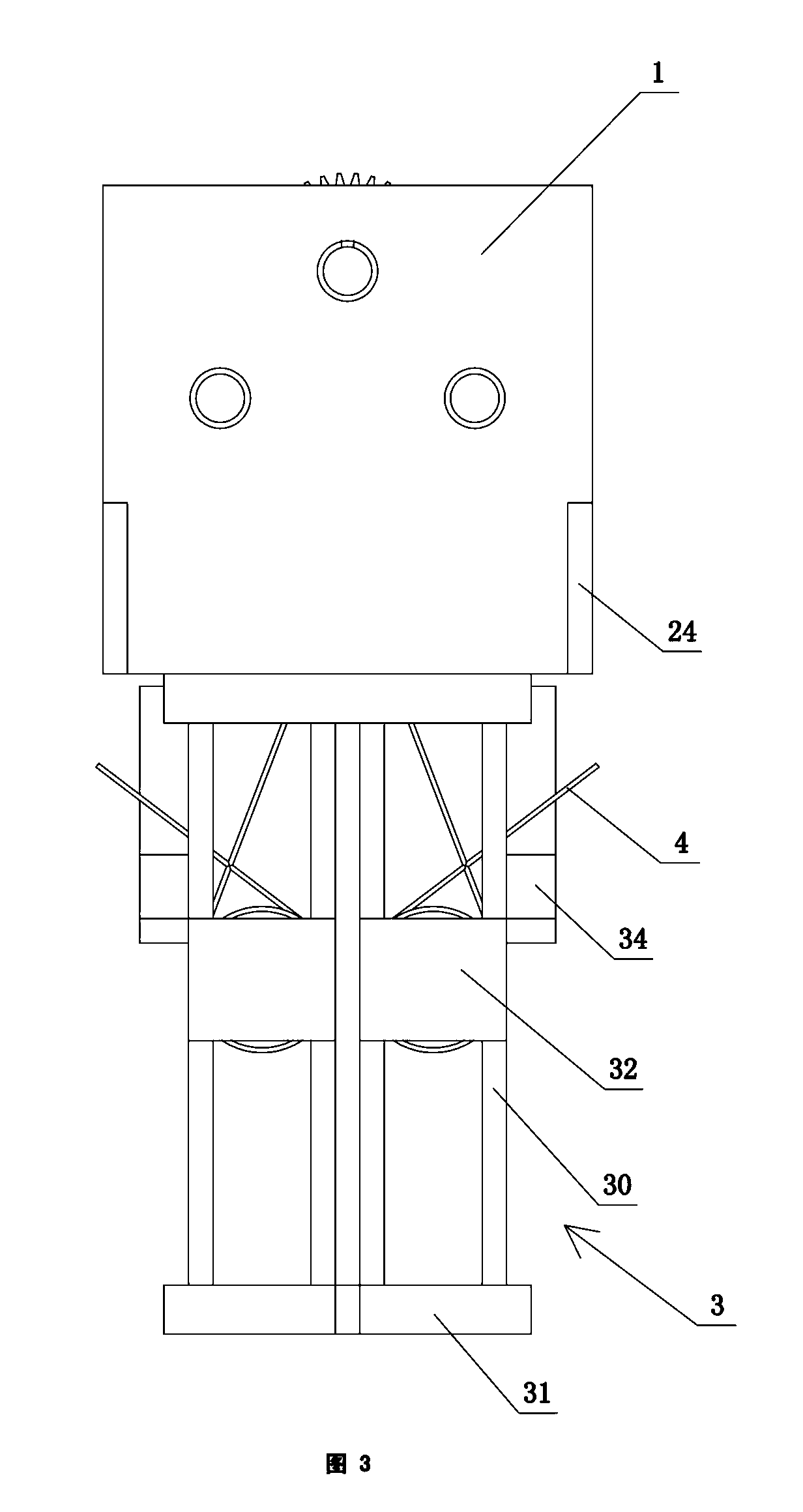

Image

  • Monofilament tension control mechanism
  • Monofilament tension control mechanism
  • Monofilament tension control mechanism

Examples


Embodiment Construction

[0022] Refer to attached figure 1 , figure 2 and image 3 . A monofilament tension control mechanism includes a main base 1 , an automatic adjustment assembly installed on the main base 1 , and a comb chain device 3 matched with the automatic adjustment assembly. The main base 1 is equipped with a main transmission wheel 10 .

[0023] Refer to attached figure 1 , figure 2 , image 3 and Figure 6 . The automatic adjustment assembly is divided into two groups, and each group of automatic adjustment assembly includes a driven inclined wheel 20, a swing wheel 21, an L-shaped swing arm 22, an adjustment belt 23 and fixedly connected to the main assembly. The base plate 10 corresponds to a balance wheel support plate 24 on the side wall. The driven inclined wheel 20 is engaged with the main transmission wheel 10, and its front part is a conical rotating part 200 for driving the adjustment belt 23 to rotate. The swing wheel 21 is connected to one end of the swing arm 22 , ...


PUM


Abstract

The invention relates to a monofilament tension control mechanism comprising a main substrate, an automatic adjusting component which is arranged on the main substrate and a comb chain device which is matched with the automatic adjusting component; a main driving wheel is assembled on the main substrate; the automatic adjusting component comprises a driven inclined wheel, a swing wheel, a swing arm, an adjusting belt and a swing wheel support plate which is fixedly connected onto the side wall of the main substrate; the driven inclined wheel is meshed with the main driving wheel; the front part of the driven inclined wheel is provided with a rotary part which is used for driving the adjusting belt to rotate and is in a conical shape; the swing wheel is connected onto one end of the swing arm; one end of the swing arm can drive the swing wheel to be connected with the swing wheel support plate in the way of swinging back and forth, and the other end of the swing arm is connected onto the swing wheel; the adjusting belt is sleeved on the rotary part and the swing wheel; the comb chain device comprises a rail frame with a guide rail rod, a slider capable of sliding on the guide rail rod and a monofilament cartridge which is rotationally arranged on the front end surface of the slider; and one side of the slider is provided with a contact rod which is in touch fit with one end of the swing arm. According to the monofilament tension control mechanism, the structure is novel, the practicality is high, and the tension of a monofilament can be adjusted and ensured in real time.

Description

technical field [0001] The invention relates to a zipper forming machine, specifically a monofilament tension control mechanism, which is assembled on a nylon zipper forming machine. Background technique [0002] With the development of human social economy and science and technology, zipper has played an increasingly important role in people's life, and it is widely used in various fields such as aerospace, military affairs, medical treatment and civilian use. As one of the three major categories of zippers, nylon zippers are closely related to our lives. For example, clothes, shoes, bags, etc. used in daily life all use nylon zippers. Class and other manufacturers of all ages. [0003] Nylon zipper is composed of nylon monofilament wrapped around the center line through a heated die. The feeding mechanism of the existing nylon zipper forming machine is generally a simple comb belt mechanism. When the nylon zipper forming machine is working, the monofilament wound on the ...

Claims


Application Information

Patent Timeline
Patent Type & Authority Applications(China)
IPC IPC(8): B65H59/10
Inventor 张田王喆吴进奇
Owner FUJIAN SBS ZIPPER SCI & TECH CO LTD
Learn More