
Stator hybrid short magnetic circuit magnetic suspension switched reluctance generator

A technology of switched reluctance and short magnetic circuit, applied in the direction of synchronous generators, etc., can solve the problems of increasing the magnetomotive force requirements of the motor, increasing the loss of the stator core, and the influence of the radial suspension force, so as to improve the suspension performance and increase the output. Power density, the effect of expanding the production range

Inactive Publication Date: 2013-03-27
JIANGSU UNIV
View PDF1 Cites 22 Cited by
  • Summary
  • Abstract
  • Description
  • Claims
  • Application Information

AI Technical Summary

Problems solved by technology

However, in this structure, only half of the stator poles are used for excitation and power generation, so excitation is difficult and power density is very low
Moreover, the motor adopts a long magnetic circuit structure, and there is a reverse magnetic field in the stator core, which not only increases the requirements for the motor's magnetomotive force, but also increases the loss of the stator core of the motor
At the same time, when the excitation winding of the motor is energized together with the suspension winding, the excitation current still has a great influence on the radial suspension force

Method used


Image

  • Stator hybrid short magnetic circuit magnetic suspension switched reluctance generator
  • Stator hybrid short magnetic circuit magnetic suspension switched reluctance generator
  • Stator hybrid short magnetic circuit magnetic suspension switched reluctance generator

Examples


Embodiment Construction

[0035] The present invention will be described in further detail below in conjunction with the accompanying drawings.

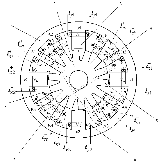
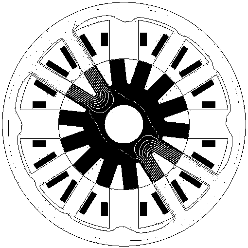
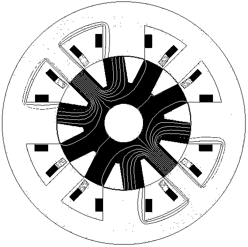
[0036] A stator hybrid short magnetic circuit magnetic levitation switched reluctance generator according to the present invention adopts a double salient pole structure with 12 poles in the stator and 14 poles in the rotor, and consists of a stator core, a rotor core, a levitation pole, a generator pole, a rotor pole, It is composed of suspension winding, excitation winding and generating winding. The inner wall of the stator core is provided with four floating poles at equal intervals of 90° along the circumferential direction ( x 1, x 2, y 1, y 2), eight generating electrodes are set at equal intervals of 30° between the four floating electrodes (A1 ~A 4 , B 1 ~B 4 ), the outer wall of the rotor core is provided with fourteen rotor poles at equal intervals along the circumferential direction. It is 12.85°, and there is a certain air gap between t...


PUM


Abstract

The invention discloses a stator hybrid short magnetic circuit magnetic suspension switched reluctance generator which is composed of a stator iron core, a rotor iron core, four suspension poles, eight power generation poles, fourteen rotor poles, four sets of suspension windings, two groups of excitation windings and two phase power generation windings. The four suspension poles are arranged on the stator iron core at equal interval, each two of the eight power generation poles are arranged between the four suspension poles at equal interval, the fourteen rotor poles are arranged on the rotor iron core at equal interval, the four sets of suspension windings are respectively wound on the four suspension poles independently, the two phase excitation windings and the two phase power generation windings are wound on the power generation poles opposite in the radial direction in lap mode, pole arcs of the suspension poles are two times of pole arcs of the power generation poles, and pole arcs of the power generation poles are equal to an arc pole of a rotor. The stator hybrid short magnetic circuit magnetic suspension switched reluctance generator adopts a hybrid stator and a short magnetic circuit structure, solves the problem of coupling of excitation, power generation and suspension, overcomes a magnetic flux reversal phenomenon, reduces magnetic motive force and stator iron core loss, and improves working efficiency and output power density.

Description

technical field [0001] The invention relates to a magnetic levitation switched reluctance generator, in particular to a stator hybrid short magnetic circuit magnetic levitation switched reluctance generator, which belongs to the electromechanical field. Background technique [0002] The switched reluctance motor adopts a double salient pole structure, the stator is wound with a concentrated winding, and the rotor has neither winding nor permanent magnet. Advantages, especially suitable for operation in harsh environments and occasions that require high speed and ultra high speed. Considering the similarity of the stator of the switched reluctance motor and the magnetic bearing stator structure, combining the magnetic bearing technology with the switched reluctance motor to form a magnetic levitation switched reluctance motor not only broadens the theory and application range of the magnetic levitation motor, but also inherits and exerts The high-speed superiority of the swi...

Claims


Application Information

Patent Timeline
Patent Type & Authority Applications(China)
IPC IPC(8): H02K19/26
Inventor 朱志莹孙玉坤王丽平姜永将蒋维婷祖层
Owner JIANGSU UNIV
Learn More