
High-voltage saturable pulse transformer serving as multi-way synchronous magnetic switch

A pulse transformer, multi-channel synchronization technology, applied in the direction of magnetic bias transformer, transformer/inductor core, transformer/inductor coil/winding/connection, etc. , the complex structure of coaxial conductors, etc.

Inactive Publication Date: 2013-03-27
NAT UNIV OF DEFENSE TECH
View PDF4 Cites 9 Cited by
  • Summary
  • Abstract
  • Description
  • Claims
  • Application Information

AI Technical Summary

Problems solved by technology

[0013] The technical problem to be solved by the present invention is to solve the problems of complex coaxial conductor structure, bulky volume, difficult expansion of coaxial conductor winding turns in the existing coaxial conductor structure saturable pulse transformer, and the existing ordinary wire-wound saturable pulse transformer. Transformers and coaxial conductor structure saturable pulse transformers cannot be used as multi-channel synchronous pulse transformers and multi-channel synchronous magnetic switches. The multi-route winding winding group parallel connection technology is adopted. On the basis of taking into account the characteristics of high boost multiple and low saturation inductance , to provide a high-voltage saturable pulse transformer with simple winding structure, small size, low cost, automatic core reset, and can be directly used as multi-channel pulse capacitor or pulse forming line ns-level synchronous magnetic switch

Method used

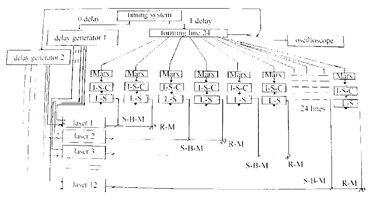
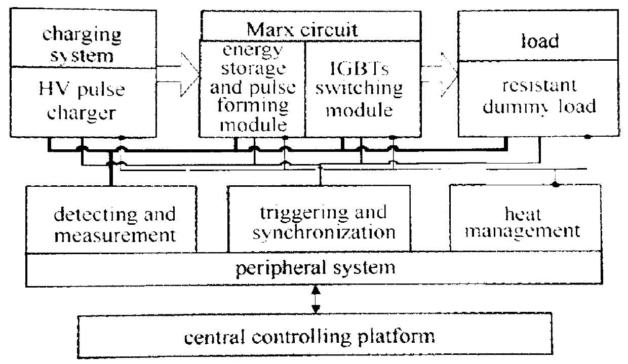

Image

  • High-voltage saturable pulse transformer serving as multi-way synchronous magnetic switch
  • High-voltage saturable pulse transformer serving as multi-way synchronous magnetic switch
  • High-voltage saturable pulse transformer serving as multi-way synchronous magnetic switch

Examples


Embodiment approach 1

[0065] Embodiment 1: The National University of Defense Technology adopts the embodiment of the present invention to design a saturable pulse transformer for line charging of 300kV / 1.75nF spiral Blumlein pulses, using a single set of secondary windings and a structure of 9 secondary sub-windings connected in parallel way (Q=1, N=9). In the saturable pulse transformer, a total of 9 (M=9) magnetic rings are used as the transformer core, and the 9 magnetic rings are divided into 3 groups (m=3), and the package size of a single magnetic ring is Φ410×Φ270×24.5 (Φ410 means the outer diameter of the magnetic ring is 410, Φ270 means the inner diameter of the magnetic ring is 270, and 24.5 means the height of the magnetic ring, unit: mm, the same below), the size of the single magnetic ring body after removing the shell package is Φ406×Φ274×20 (unit: mm); the primary winding of the transformer is composed of 3 (m=3) single-turn sub-windings connected in parallel, and the wire-wound sec...

Embodiment approach 2

[0066] Embodiment 2: The National University of Defense Technology adopts the embodiment of the present invention to design a high-voltage saturable pulse transformer with a multi-channel parallel structure of wire-wound windings, which is used to charge a 40kV / 175nF pulse capacitor and also serves as the main switch for discharging the capacitor. A total of 6 (M=6) magnetic rings are used as the transformer magnetic core, and the 6 magnetic rings are divided into 6 groups, and each group has a magnetic ring; the package size of a single magnetic ring is Φ280×Φ140×25 (unit: mm), remove The body size of the single magnetic ring packaged in the shell is Φ276×Φ144×20 (unit: mm). The primary winding of the transformer is composed of 6 (m=M=6) single-turn sub-windings connected in parallel, the wire-wound secondary winding has only 1 group (Q=1) of secondary windings, and 12 (N=12) secondary windings The windings are evenly distributed in parallel along the circumferential directio...

Embodiment approach 3

[0067] Embodiment 3: The National University of Defense Technology adopts the embodiment of the present invention to design a saturable pulse transformer to replace a 3-stage all-solid-state Marx generator with a 3-stage gas switch, using a 3-stage Marx capacitor and a grounded inductance unit for parallel synchronous charging, and 3 groups of saturable pulses The working mode of synchronous saturation of transformer secondary winding and synchronous discharge of 3-level Marx capacitors in series. In the low-inductance wire-wound saturable pulse transformer, a total of 6 (M=6) magnetic rings are used as the transformer core, and the 6 magnetic rings are divided into 6 groups. The package size of a single magnetic ring is Φ280×Φ140×25 (unit: mm), the size of the single magnetic ring body after removing the shell package is Φ276×Φ144×20 (unit: mm); the primary winding of the transformer is composed of 6 (m=M=6) single-turn sub-windings connected in parallel, The secondary windin...


PUM

PropertyMeasurementUnit
Thicknessaaaaaaaaaa
Thicknessaaaaaaaaaa
Widthaaaaaaaaaa

Abstract

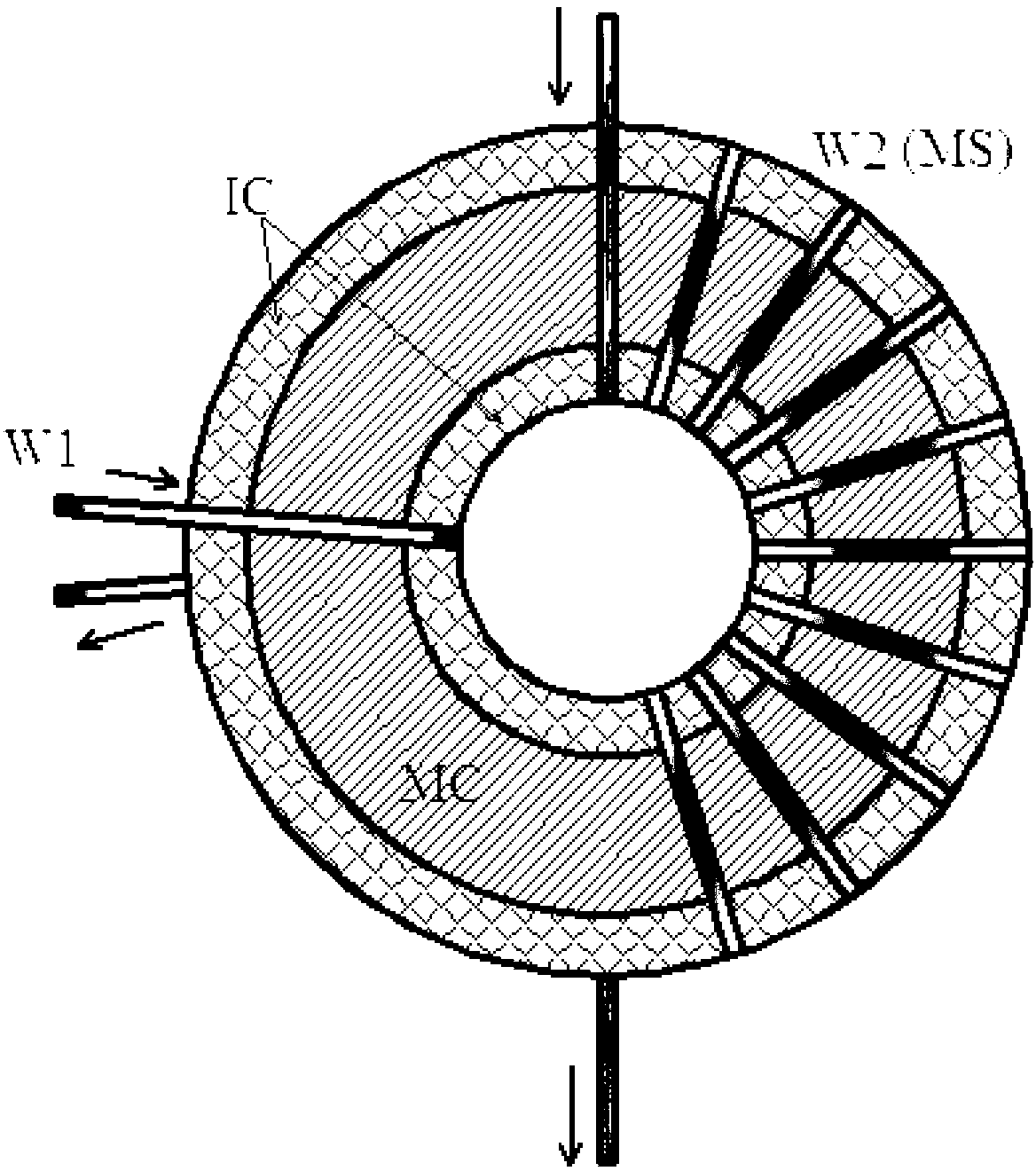
The invention discloses a high-voltage saturable pulse transformer serving as a multi-way synchronous magnetic switch, aiming at solving the problems existing in the conventional saturable transformer that the characteristics of high step-up multiple and low saturation inductance are difficultly balanced and the conventional saturable transformer cannot be used as a multi-path synchronous pulse transformer or a multi-path synchronous magnetic switch. The high-voltage saturable pulse transformer consists of a transformer inner core part, a transformer primary winding part and a transformer secondary winding part, wherein a parallel structure that m groups of magnetic rings are wrapped by m paths of primary sub-winding groups respectively is adopted; secondary windings are divided into Q groups and are uniformly distributed in the circumferential direction of the magnetic rings; and each group of secondary windings also consists of N paths of wound secondary sub-windings. According to the high-voltage saturable pulse transformer, the step-up multiple can be improved to m times of the turns Ns of secondary windings, meanwhile, synchronous step-up of Q 1:m*Ns pulse transformers is realized, the saturation inductance of transformer secondary windings of the same turns can be approximately reduced by N times, and Q groups of independent transformer secondary windings can be used as Q paths of independent magnetic switches to realize ns-level synchronous conduction.

Description

technical field [0001] The invention relates to a saturable pulse transformer in the technical field of high-power pulse modulation, in particular to a high-voltage saturable pulse transformer as a multi-channel synchronous magnetic switch which adopts a grouped parallel structure of multi-route winding windings. Background technique [0002] Pulse power modulation technology is an electrophysical technology that quickly compresses, converts or directly releases "slow" stored electric or magnetic field energy with high density to the load, and the voltage conversion and switching technology is the key. In recent years, pulse power modulation technology has been well applied in many fields such as high-power microwave, high-power pulse laser, shock wave generator, dielectric barrier discharge, material surface treatment, industrial waste gas and wastewater treatment, food sterilization and biomedicine, and These applications place demands on pulse power modulators for high po...

Claims


Application Information

Patent Timeline
IPC IPC(8): H01F19/08H01F27/26H01F27/30
Inventor 张瑜刘金亮
Owner NAT UNIV OF DEFENSE TECH
Learn More