Process water regulating tank repair system and method

A technology for repairing systems and regulating pools, applied in chemical instruments and methods, building maintenance, water/sewage treatment, etc., can solve problems such as economic loss, difficulty, and time-consuming, and achieve low head requirements, reliable connection, and simple operation Effect

Active Publication Date: 2013-03-27
中城建胜义(深圳)环境科技有限公司 +2
View PDF6 Cites 1 Cited by
  • Summary
  • Abstract
  • Description
  • Claims
  • Application Information

AI Technical Summary

Problems solved by technology

The water inlet of the adjustment tank is generally located below the water level in the adjustment tank, and there is a greater risk of blocking the HDPE pipe under the process water
In addition, since it is difficult to completely stop water from the drainage chute or drainage shaft in the reservoir area, once the water inlet of the adjustment pool is blocked, the water level in the pipeline connecting the reservoir area and the adjustment pool will rise rapidly to be equal to the water level of the reservoir area, thereby affecting The blocked port of the water inlet forms a large water pressure, which makes the blocked port flushed open
2. It takes a long time and is difficult to transfer the water stored in the adjustment pool to the reservoir area
It is time-consuming and costly to transfer tens of thousands of cubic meters of process water through the pump over the initial dam to the reservoir area higher than the regulating tank
The more prominent problem is that during the period of pumping water and repairing the adjustment tank, the return water is interrupted, and the factory will inevitably stop production, which will cause huge economic losses

Method used


Image

  • Process water regulating tank repair system and method
  • Process water regulating tank repair system and method
  • Process water regulating tank repair system and method

Examples


Embodiment Construction

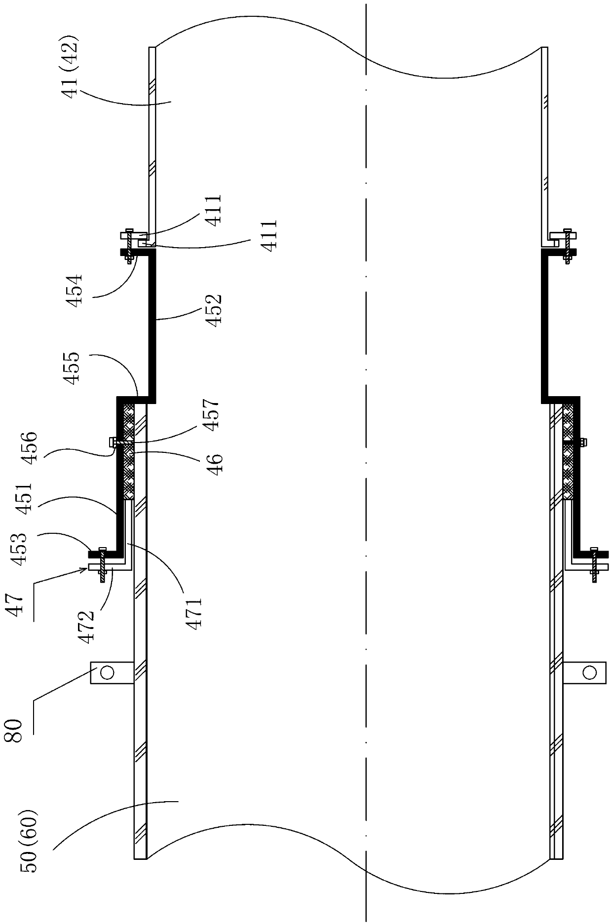
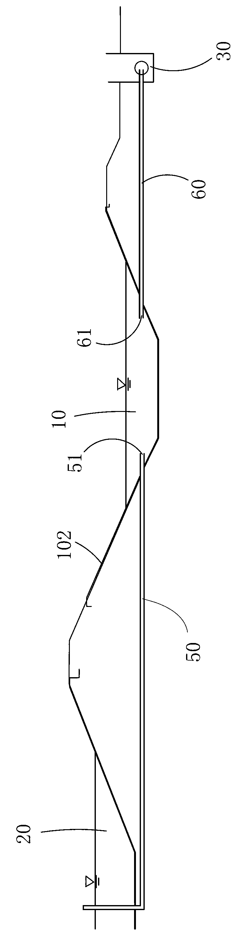
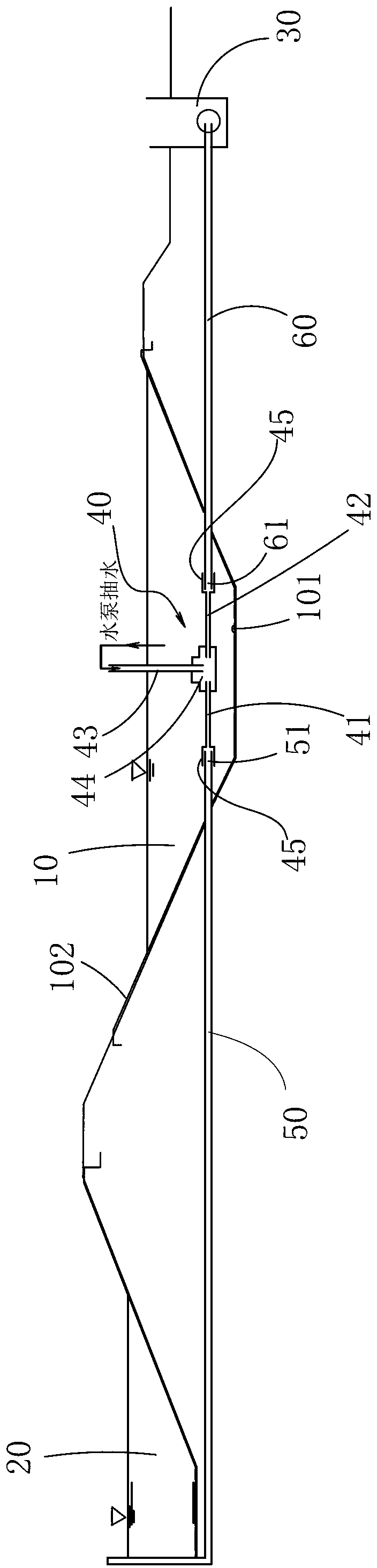
[0040] like Figure 2-3As shown, in a process water regulating tank repair system of the present invention, the regulating tank 10 communicates with the bottom of the storage area 20 through the first delivery pipe 50, and the process water in the storage area is introduced into the water inlet 51 of the first delivery pipe 50 for adjustment. pool, and the regulating pool is also communicated with the return water pump room 30 that pumps the process water back to the factory through the second delivery pipe 60, and the process water is exported from the water outlet 61 of the second delivery pipe 60 to the regulating pool. As the conveying pipes, the first conveying pipe and the second conveying pipe can be HDPE pipes or PE pipes, and high-density polyethylene pipes (HDPE pipes) are generally required for process water with a high concentration of pollutants. figure 2 The anti-seepage film 102 of the regulating tank wall in the center has a leakage point 101. In order to drai...


PUM


Abstract

The invention discloses a process water regulating tank repair system which comprises a three-way pipeline system (40) and is particularly provided with reducer joints (45). Outer ports of two communicating pipes (41 and 42) of the three-way pipeline system are respectively and correspondingly communicated with a water inlet (51) and a water outlet (61) through the reducer joints; a third communicating pipe (43) is fixed on the wall of a regulating tank, and an outer port (431) of the third communicating pipe (43) is higher than the liquid level of a reservoir area; and a water pump pumps process water in the regulating tank into the third communicating pipe. The process water in the regulating tank is very convenient to be pumped into the three-way pipeline system, flows automatically into a water return pump room and then is conveyed back to a factory for recycling, so that the regulating tank is dried up under the condition of not interrupting production, and further a seepage-proofing membrane of the regulating tank is repaired. According to the invention, the requirement on the water pump is low; return water is not influenced by the flow rate of the water suction pump, so that the safety of the water return pump is ensured; and the reducer joints are provided specially for connecting the conveying pipes and the three-way pipeline system, the water inlet is not required to be sealed, the connection is reliable, and thus the danger to workers during underwater operation can be avoided.

Description

technical field [0001] The invention relates to a repairing system and a repairing method for an anti-seepage film under process water regulating tanks of tailings ponds and industrial waste slag storage yards. Background technique [0002] Regulating ponds are an integral part of tailings ponds and industrial waste dumps, and play multiple roles in water return, flood storage and flood regulation. Due to recycling, the water used to transport industrial waste residues generally has a high content of pollutants, and is usually called process water. In order to prevent process water leakage from polluting groundwater and soil, process water adjustment tanks usually need to be treated with anti-seepage membranes. After the slurry transporting industrial waste enters the storage yard, the solid waste settles in the reservoir area, and the clarified process water enters the drainage chute or drainage shaft, and then flows into the regulating pool through the conveying pipeline ...

Claims


Application Information

Patent Timeline
Patent Type & Authority Applications(China)
IPC IPC(8): E04G23/02C02F1/00
Inventor 周晓晖刘宁
Owner 中城建胜义(深圳)环境科技有限公司
Why Eureka
Try Eureka