A/B shaft parallel mechanism

A parallel, B-axis technology, used in manipulators, metal processing machinery parts, large fixed members, etc., can solve the problems of large motion mass, large installation space, and high manufacturing cost, and achieve a small motion mass, compact structure, and easy assembly. Effect

Inactive Publication Date: 2013-03-27
TIANJIN UNIV
View PDF7 Cites 7 Cited by
  • Summary
  • Abstract
  • Description
  • Claims
  • Application Information

AI Technical Summary

Problems solved by technology

[0002] At present, robot joints, especially wrist joints, are mostly realized by gear transmission and series structure, which has complex structure, difficult installation, and high manufacturing cost.
[0003] The two-degree-of-freedom rotors used as machine tool accessories are mostly in series, with large moving mass and poor rigidity
Patent CN100464946C proposes a parallel A / B-axis spindle head structure, which overcomes the shortcomings of the serial rotor head, but its structure is asymmetrical, and the installation space required by the mechanism is relatively large

Method used


Image

  • A/B shaft parallel mechanism
  • A/B shaft parallel mechanism
  • A/B shaft parallel mechanism

Examples


Embodiment Construction

[0013] The present invention will be further described in detail below in combination with specific embodiments.

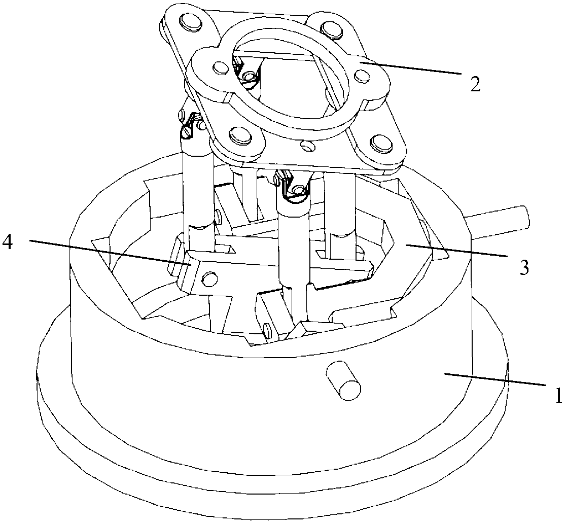
[0014] Such as figure 1 As shown, an A / B-axis parallel mechanism of the present invention includes a fixed platform 1 , a moving platform 2 , and a first branch 3 and a second branch 4 connecting the fixed platform 1 and the moving platform 2 .

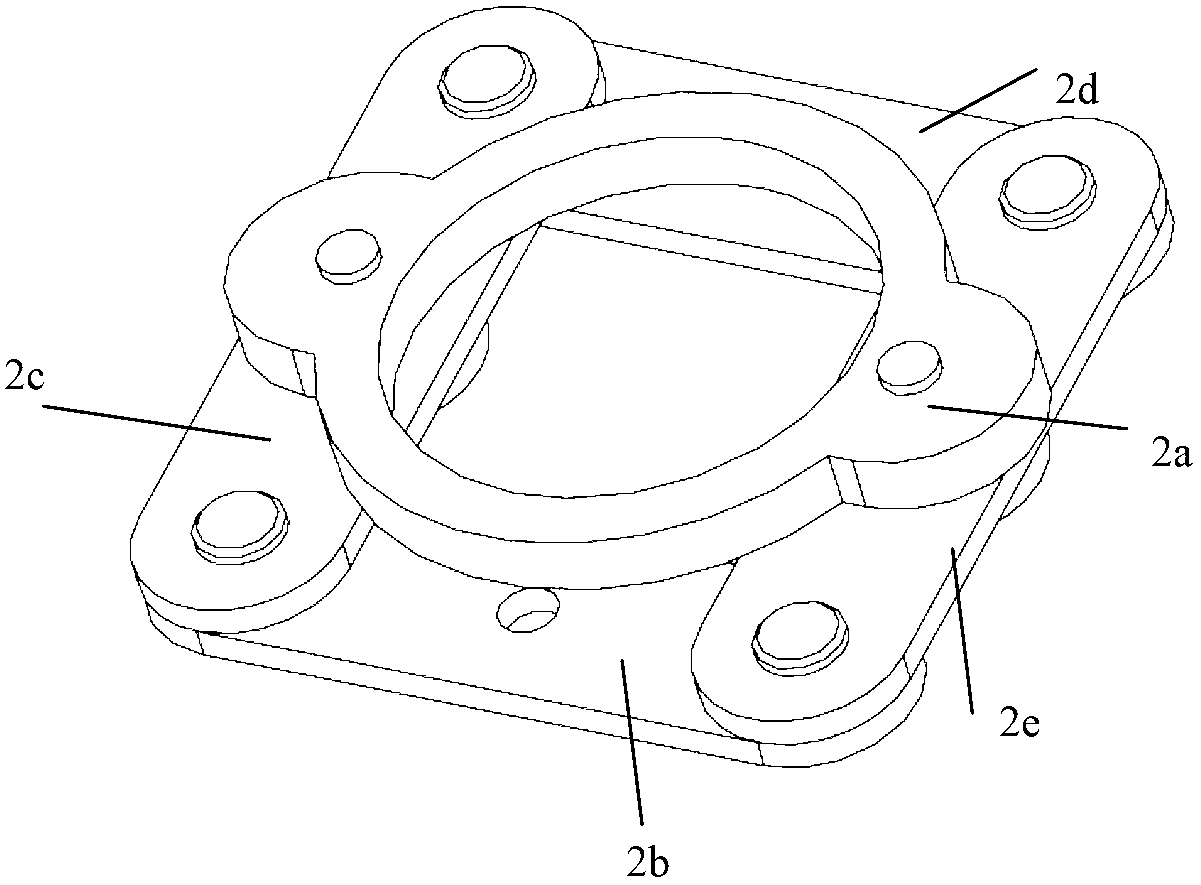
[0015] Such as figure 2 As shown, the moving platform 2 includes a main platform 2a and four connecting rods 2b~2e, and the four connecting rods 2b~2e are connected by rotating pairs to form a plane parallelogram structure, and the axes of the four rotating pairs are perpendicular to the plane The plane where the parallelogram is located; the main platform 2a is respectively connected with a group of opposite side connecting rods 2b, 2d of the parallelogram of the plane through a rotary pair whose axis is perpendicular to the plane of the parallelogram, and the two rotary pairs on the main platform 2a The connecting li...


PUM


Abstract

The invention discloses an A / B shaft parallel mechanism, comprising a fixed platform, a movable platform, a first branch and a second branch, wherein the first branch and the second branch are connected between the fixed platform and the movable platform; the movable platform comprises a main platform and four connecting rods; four connecting rods are connected through a revolute pair to form a plane parallelogram structure; a first driving arm, two first driven arms and the movable platform form a group of plane parallelogram structures inside the first branch, so as to prevent the movable platform from translating along the axis direction of the revolute pair on the driving arm; a second driving arm, two second driven arms and the movable platform form another group of plane parallelogram structures inside the second branch, so as to prevent the movable platform from translating along the axis direction of the revolute pair on the second driving arm; and the two-dimensional rotation of the movable platform is achieved by controlling rotation of the first driving arm and the second driving arm. The A / B shaft parallel mechanism is simple in construction, compact in structure, small in motion mass, convenient to assemble, and easy to control, and can be used for robot joints or machine tool accessories.

Description

technical field [0001] The invention belongs to the field of machinery, and in particular relates to a parallel mechanism with two rotational degrees of freedom without accompanying motion applicable to robot joints or machine tool accessories. Background technique [0002] At present, robot joints, especially wrist joints, are mostly realized by gear transmission and series structure, which is complex in structure, difficult to install, and high in manufacturing cost. [0003] Most of the two-degree-of-freedom rotors used as machine tool accessories are connected in series, with large moving mass and poor rigidity. Patent CN100464946C proposes a parallel A / B-axis spindle head structure, which overcomes the shortcomings of the series-type rotor, but its structure is asymmetrical, and the installation space required by the mechanism is relatively large. Contents of the invention [0004] Aiming at the above-mentioned prior art, the present invention provides an A / B-axis pa...

Claims


Application Information

Patent Timeline
Patent Type & Authority Applications(China)
IPC IPC(8): B25J17/00B23Q1/44
Inventor 赵学满王攀峰宋轶民孙涛董罡
Owner TIANJIN UNIV
Why Eureka
Try Eureka