A rotating shaft type model hinged fixing structure and rotating shaft supporting method

A technology for fixing structures and models, applied in the field of aerospace engineering, can solve problems such as the inability to ensure that the fixed sleeve of the model does not move, the simulation that affects the flight state of the model, and the simulation of the elastic torsion that cannot be realized, so as to reduce deformation and improve The effect of supporting stiffness, relaxing torsional degrees of freedom

Active Publication Date: 2020-12-18
CHINA ACAD OF AEROSPACE AERODYNAMICS
View PDF7 Cites 0 Cited by
  • Summary
  • Abstract
  • Description
  • Claims
  • Application Information

AI Technical Summary

Problems solved by technology

[0004] (1) The position control of the nodes is not accurate. During the design process, it is hoped that the fixed sleeve of the model cannot move in translation, but only rotates
However, in the actual model connection process, the rod fixing sleeve is fixed by the model, which can only ensure that the rod fixing sleeve does not move in translation, but cannot guarantee that the model fixing sleeve does not move in translation
[0005] (2) The torsion center of the joint is not accurate. During the design process, it is hoped that the model can rotate around the fixed sleeve of the model, but in the actual model connection process, the center of rotation is the root of the fixed sleeve of the joint.
[0006] (3) At the static moment of the installation, since the thin wall is usually relatively thin, it will produce a certain elastic deformation under the gravity of the model, which will also affect the simulation of the actual flight state of the model
[0007] (4) The test has high requirements for the thickness design of the thin-walled beam. If the thickness of the thin-walled beam is too large, the simulation of elastic torsion cannot be realized; if the thickness of the thin-walled beam is too small, the purpose of supporting the model cannot be achieved

Method used


Image

  • A rotating shaft type model hinged fixing structure and rotating shaft supporting method
  • A rotating shaft type model hinged fixing structure and rotating shaft supporting method
  • A rotating shaft type model hinged fixing structure and rotating shaft supporting method

Examples


Embodiment Construction

[0032] The present invention will be described in detail below in conjunction with the accompanying drawings and examples.

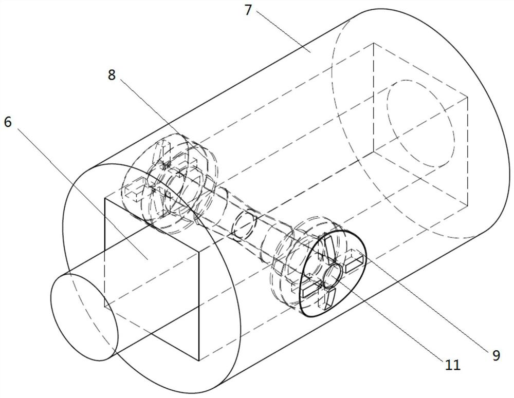
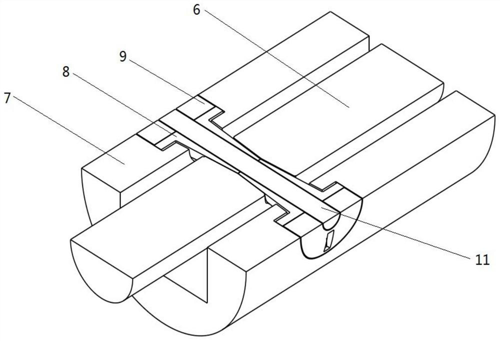
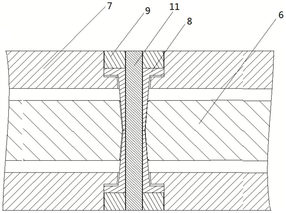
[0033] Such as figure 1 , figure 2 , image 3 As shown, a rotating shaft type model hinge fixing structure includes: a support rod 6, a rotating shaft member 11, two clips 8, and two end fixing nuts 9; the support rod 6 is radially symmetrically arranged with two Round table hole 10( Figure 4 As shown), the upper bottom of the round platform is located on the axis of the pole; the model 7 is provided with installation through holes radially, the pole 6 is located inside the model and the round platform hole on the pole is coaxial with the above-mentioned installation through hole, and the rotating shaft rod 11 is located at In the above-mentioned coaxial hole, two clips 8 with a central round hole are set on the rotating shaft rod 11 and placed in the above-mentioned round table hole and the installation through hole, and the two ends of the rotatin...


PUM


Abstract

The invention relates to a hinging fixing structure of a rotating shaft type model and a rotating shaft supporting method. The hinging fixing structure comprises a supporting rod, a rotating shaft rodpiece, two clamping pieces and two end portion fixing nuts. The supporting rod is symmetrically provided with two truncated cone holes in the radial direction, and the upper bottom of a truncated cone is positioned on the axis of the supporting rod. The model is radially provided with an installation through hole. The supporting rod is positioned in the model, and the truncated cone holes in thesupporting rod are coaxial with the installation through hole. The rotating shaft rod piece is positioned in a coaxial hole. The two clamping pieces with central circular holes sleeve the rotating shaft rod piece and are arranged in the truncated cones and the installation through hole. Threads are arranged at two ends of the rotating shaft rod piece and are matched with the end portion fixing nuts to ensure that the two clamping pieces are tightly pressed and the model has the freedom of rotation only around the rotating shaft rod piece. By means of the hinging fixing structure of the rotating shaft type model and the rotating shaft supporting method, the vibration mode of the model can be simulated more accurately, so that the purposes of improving test precisions and increasing the accuracy of wind tunnel test simulation are realized.

Description

technical field [0001] The invention relates to a hinged fixed structure of a rotating shaft type elastic model, which belongs to the field of aerospace engineering. Background technique [0002] When carrying out some dynamic wind tunnel tests, it is necessary to design the model and provide elastic hinged fixed support for the model. The support position is usually the node position of the mode shape of the model vibration, and the model can rotate but cannot be translated at the node position. Usually, the design method of the elastic support of the model is: use the slender thin-walled beam structure to realize the simulation of the elastic hinge point. [0003] The existing model hinge fixed structure has the following problems: [0004] (1) The position control of the nodes is not accurate. During the design process, it is hoped that the fixed sleeve of the model cannot move in translation, but only rotates. However, in the actual model connection process, the rod fi...

Claims


Application Information

Patent Timeline
Patent Type & Authority Patents(China)
IPC IPC(8): F16C11/04F16C11/10G01M9/04
CPCF16C11/04F16C11/10G01M9/04
Inventor 侯英昱季辰刘子强吕计男
Owner CHINA ACAD OF AEROSPACE AERODYNAMICS
Why Eureka
Try Eureka