Sewage treatment membrane separation unit, sewage treatment membrane module, and method for sewage treatment through utilizing membrane module

A technology for sewage treatment and membrane separation, applied in the field of environmental engineering, can solve the problems of ineffective use of heat, large system area, unfavorable protein separation, etc. The effect of reducing the concentration polarization phenomenon

Inactive Publication Date: 2014-12-03
BEIJING FORESTRY UNIVERSITY
View PDF4 Cites 0 Cited by
  • Summary
  • Abstract
  • Description
  • Claims
  • Application Information

AI Technical Summary

Problems solved by technology

[0008] Kai Yu Wang et al. from Singapore used forward osmosis and membrane distillation to concentrate protein solutions (Kai yu Wang et. Integrated forward osmosis-membrane distillation (FO-MD) hybrid system for the concentration of protein solutions, Chemical Engineering Science.66 (2011), 2424-2430.), first of all, the separation system used in this study is mainly used to separate and purify macromolecular substance protein, and secondly, the separation system needs to drive solution in forward osmosis (FO) system and membrane distillation ( MD) system for repeated circulation, and for practical engineering applications, the dispersed longer pipeline is also an unfavorable factor for reducing heat loss, especially for the separation of biologically active proteins; the third is that the research is in The FO and MD systems need to cool and heat the drive solution respectively, which lead to high energy consumption of the system used in this research, and the heat cannot be effectively used, which is not conducive to energy conservation; the fourth is that the system occupies a large area , thus limiting its promotion and application

Method used


Image

  • Sewage treatment membrane separation unit, sewage treatment membrane module, and method for sewage treatment through utilizing membrane module
  • Sewage treatment membrane separation unit, sewage treatment membrane module, and method for sewage treatment through utilizing membrane module
  • Sewage treatment membrane separation unit, sewage treatment membrane module, and method for sewage treatment through utilizing membrane module

Examples


Embodiment 1

[0083] 1. Forward osmosis treatment

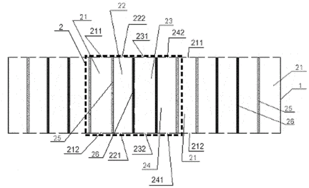
[0084] In this embodiment, 30 permeable membranes 25 and 30 microporous hydrophobic membranes 26 are used in the sewage treatment flat membrane module, that is, there are 15 membrane separation units 2 in the sewage treatment membrane module;

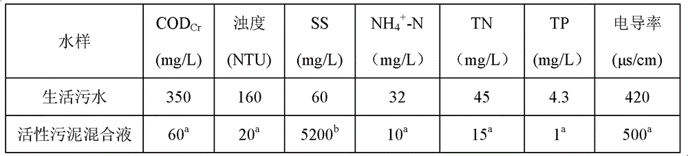
[0085] The activated sludge mixed solution flows into the sewage chamber of the membrane module from the inlet 211 of the sewage chamber 21 at a flow rate of 50 cm / s; the driving liquid sodium chloride solution flows from the first driving liquid chamber 22 to The inlet 221 and the inlet 241 of the second driving liquid chamber 24 flow into the first and second driving liquid chambers 22 and 24 of the membrane module, wherein the temperature of the sodium chloride solution is 40°C, the concentration is 1.5mol / L, and the flow rate is 50cm / s;

[0086] The activated sludge mixed liquid and the driving liquid are separated by the osmotic membrane 25. Due to the high osmotic pressure of the driving liq...

Embodiment 2

[0090] In the membrane module, except that 16 permeable membranes 25 and 16 microporous hydrophobic membranes 26 are used in total, that is, there are 8 membrane separation units 2 in the membrane module for sewage treatment, the rest are the same as in Example 1.

[0091] In the process of forward osmosis treatment, except that the flow rate of the sewage activated sludge mixture is 70cm / s; the concentration of the drive solution is 1.5mol / L, the temperature is 40°C, and the flow rate is 70cm / s; the average membrane effluent flux of the permeable membrane 25 4.8L / (m 2 · h) except that the others are the same as in Example 1.

[0092] During the membrane distillation process, except that the temperature of the clear water is 8°C, the flow rate is 50cm / s; the average membrane water flux of the hydrophobic microporous membrane 26 is 4.8L / (m 2 · h) except that the others are the same as in Example 1.

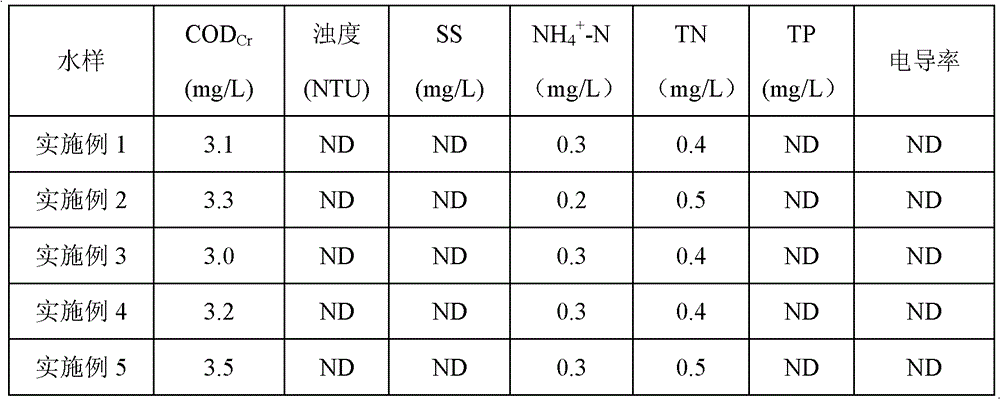
[0093] The water quality performance testing indicators of the treated efflu...

Embodiment 3

[0095] In the membrane module, except that 16 permeable membranes 25 and 16 microporous hydrophobic membranes 26 are used in total, that is, there are 8 membrane separation units 2 in the membrane module for sewage treatment, the rest are the same as in Example 1.

[0096] In the forward osmosis treatment process, except that the flow rate of the sewage activated sludge mixture is 10cm / s; the concentration of the drive solution is 1.5mol / L, the temperature is 40°C, and the flow rate is 70cm / s; the average membrane effluent flux of the permeable membrane 25 3.9L / (m 2 · h) except that the others are the same as in Example 1.

[0097] During the membrane distillation process, except that the temperature of the clear water is 8°C, the flow rate is 15cm / s; the average membrane water flux of the hydrophobic microporous membrane 26 is 4.0L / (m 2 · h) except that the others are the same as in Example 1.

[0098] The water quality performance testing indicators of the treated effluent...


PUM

PropertyMeasurementUnit
pore sizeaaaaaaaaaa

Abstract

The invention provides a sewage treatment membrane module and a method for the sewage treatment through utilizing the membrane module. The membrane module comprises a shell and at least two membrane separation units arrayed in parallel and positioned in the shell, wherein the shell is cuboid or cubic in shape, the periphery of the shell is closed, and two ends of the shell are open; each of the membrane separation units is composed of a sewage chamber, a first driving liquid chamber, a clear water chamber and a second driving liquid chamber which are sequentially connected and are arrayed in parallel, and all the chambers are separated through organic polymer membranes; and especially the flow directions of sewages in the sewage chambers are opposite to the flow directions of driving liquids in the driving liquid chambers. The method for the sewage treatment through utilizing the membrane module has the advantages of operation under no pressure, light membrane pollution degree, low energy consumption, good treated outlet water quality, and realization of the reuse of reclaimed water.

Description

technical field [0001] The invention belongs to the technical field of environmental engineering and relates to sewage treatment and reclaimed water reuse technology, in particular to a flat membrane module which can be used in a membrane bioreactor and a method for treating sewage by using the membrane module. Background technique [0002] Membrane bioreactor is a new type of water treatment technology that combines membrane separation unit and biological treatment unit. It replaces the terminal secondary sedimentation tank of traditional biological treatment technology with membrane modules, and has significant advantages over traditional activated sludge technology. For example, it can maintain a high concentration of activated sludge in the bioreactor, increase the organic load of biological treatment, thereby reducing the area occupied by sewage treatment facilities, and reduce the amount of residual sludge by maintaining low sludge load, without being affected by sludge...

Claims


Application Information

Patent Timeline
Patent Type & Authority Patents(China)
IPC IPC(8): B01D63/08B01D61/00C02F1/44C02F3/12C02F3/10
CPCY02W10/10
Inventor 朱洪涛
Owner BEIJING FORESTRY UNIVERSITY
Why Eureka
Try Eureka