A power lowering type tower pumping unit

A tower pumping unit and power release technology, which is applied in the fields of production fluids, wellbore/well components, earth-moving drilling, etc., can solve the problems of inconvenient unloading, inconvenient maintenance, and large reversing impact, and reduce production costs. , The effect of giving way is convenient and the friction force is reduced

Active Publication Date: 2015-07-29
HENAN XINYU PETROLEUM MACHINERY MFG
View PDF10 Cites 0 Cited by
  • Summary
  • Abstract
  • Description
  • Claims
  • Application Information

AI Technical Summary

Problems solved by technology

The conventional beam pumping unit has a small stroke, heavy weight, large footprint, unsatisfactory balance effect, large output torque fluctuation of the gearbox and low pumping efficiency
Although the tower pumping unit has the advantages of long stroke, light weight, small footprint, energy saving, etc., most of them still have inconvenient maintenance, operation abdication, inconvenient unloading when doing underground power demonstration, large reversing impact, and no loss of load Defects such as protection, its uniform movement makes the load of the oil well pump not change uniformly during the suction process
[0003] In addition, although the existing pumping unit is equipped with a brake device, due to the harsh working environment and the influence of various disturbances, the brake device sometimes fails, which seriously threatens the operation safety.

Method used


Image

  • A power lowering type tower pumping unit
  • A power lowering type tower pumping unit
  • A power lowering type tower pumping unit

Examples


Embodiment Construction

[0051] The present invention will be further described below in conjunction with the accompanying drawings and specific embodiments.

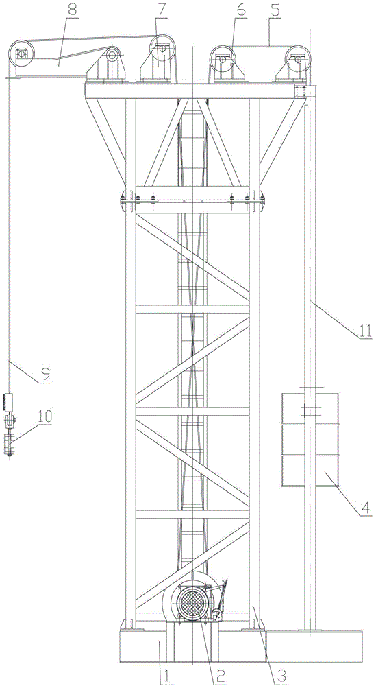
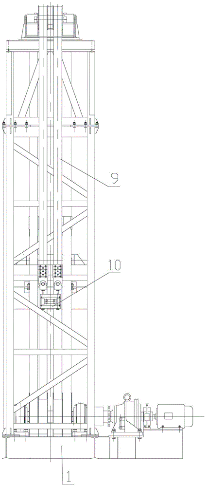
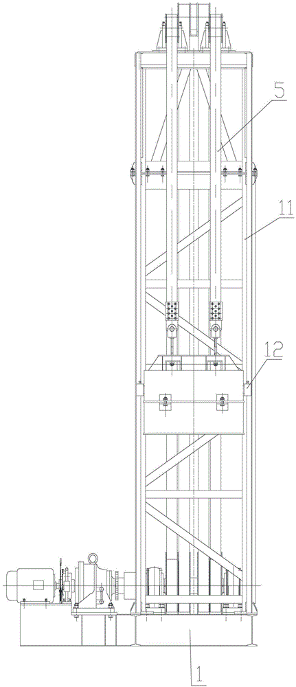
[0052] combine Figure 1-Figure 3 , The power lowering tower pumping unit of this preferred embodiment includes a base 1, a tower 3, a power system 2 connected to the base 1, a front sling traction system and a rear sling traction system. The tower 3 is a combined structure, which is connected by multiple tower sections, and the tower section can be increased or decreased according to site requirements to raise or lower the height of the tower; or the tower is set as an integral structure, and the frame is an integral In the structure, there is no need to disassemble and assemble, which simplifies the construction procedure and is suitable for low tower occasions.

[0053] Among them, such as Figure 4 , the power system 2 includes a sequentially connected motor 13, a planetary cycloid reducer 17 and a reel 21; the input end of the motor 13 a...


PUM


Abstract

The invention discloses a power-lowering tower-type oil pumping unit, which comprises a base (!), a tower (3), a power system (2) which is connected onto the base (1), a front sling traction system and a rear sling traction system. The power system (2) comprises a motor (13), a speed reducer (17) and a winding drum (21) which are sequentially connected. The motor (13) is connected with a control system. An electric hydraulic block brake (16) with a manual operation function is arranged at the input end of the speed reducer (17). A manual brake (56) is arranged at the output end of the speed reducer (17), and comprises a brake disc (52) which is arranged on the output shaft of the speed reducer (17) and a brake hook (53) which is arranged on the base (1). The brake disc (52) and the brake hook (53) form a ratchet structure. When the brake disc (52) and the brake hook (53) are engaged, the power of the motor (13) is prevented from being further transmitted; and when the brake disc (52) and the brake hook (53) are disengaged, the power of the motor (13) is normally transmitted. The electric hydraulic block brake (16) and the manual brake (56) form a dual-safe brake system.

Description

technical field [0001] The invention relates to the technical field of pumping units, in particular to a power lowering type tower pumping unit. Background technique [0002] In the process of oil production in oil field, pumping unit is one of the main oil production equipment. The conventional beam pumping unit has small stroke, heavy weight, large land occupation, unsatisfactory balance effect, large output torque fluctuation of reduction box and low pumping efficiency. Although the tower pumping unit has the advantages of long stroke, light weight, small footprint, energy saving, etc., most of them still have inconvenient maintenance, operation abdication, inconvenient unloading when doing underground power demonstration, large reversing impact, and no loss of load Defects such as protection, its uniform movement makes the load of the oil well pump not change uniformly during the suction process. [0003] In addition, although the existing pumping unit is equipped with...

Claims


Application Information

Patent Timeline
Patent Type & Authority Patents(China)
IPC IPC(8): E21B43/00B66D5/00
Inventor 娄本和
Owner HENAN XINYU PETROLEUM MACHINERY MFG
Why Eureka
Try Eureka