Defibrillator output stage with H bridge circuit and diphase sawtooth square wave defibrillation high-voltage discharge method

A defibrillator and output stage technology, applied in the field of medical electronics, can solve the problems of difficult individualized precise control, large energy control deviation, and only one wave, etc., to achieve the improvement of the success rate of electric shock synchronous defibrillation, improve the success rate, and avoid The effect of the initial voltage requirement on

Active Publication Date: 2013-03-20
久心医疗科技(苏州)有限公司
View PDF7 Cites 21 Cited by
  • Summary
  • Abstract
  • Description
  • Claims
  • Application Information

AI Technical Summary

Problems solved by technology

Although the above patents and biphasic defibrillation waves are used, the normal phase and reverse phase are essentially only one wave, which is in the form of exponential decay and decline.
Its main disadvantages are: (1) The peak part of the exponential wave exceeds the defibrillation threshold, which wastes energy and is likely to cause excessive stimulation and damage the myocardium; (2) The energy control deviation is large, and the energy released by the defibrillator depends on the chest Impedance adjustment is difficult to achieve individualized and precise control, especially for patients with extremely high or low impedance; (3) The peak part of the exponential wave requires a higher initial voltage of the capacitive energy storage device and a higher withstand voltage. Dither output stage

Method used


Image

  • Defibrillator output stage with H bridge circuit and diphase sawtooth square wave defibrillation high-voltage discharge method
  • Defibrillator output stage with H bridge circuit and diphase sawtooth square wave defibrillation high-voltage discharge method
  • Defibrillator output stage with H bridge circuit and diphase sawtooth square wave defibrillation high-voltage discharge method

Examples


Embodiment Construction

[0033] Further set forth and illustrate the present invention below in conjunction with the preferred embodiment shown in accompanying drawing:

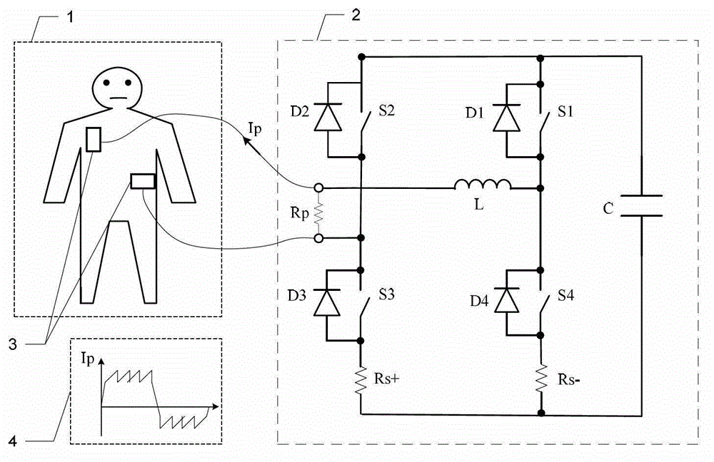
[0034] Refer to attached figure 1 , a biphasic sawtooth square wave high-voltage discharge method for cardiac defibrillation, that is, through a defibrillator output stage 2 including an H-bridge, a series of bridge switches S1~S4 combinations and control strategies are preset , the electric energy in the accumulator C is delivered to the patient's body 1 via the defibrillation electrodes 3 in the form of biphasic sawtooth pulses 4 (hereinafter referred to as Rp) to perform a rapid high-voltage electric shock discharge, so as to terminate the internal defibrillation. Ventricular fibrillation, to achieve the purpose of timely rescue of patients. The high-voltage defibrillation discharge method of the present invention with biphasic sawtooth rectangular waveform adopted in this embodiment provides a defibrillation discharge current i...


PUM


Abstract

The invention belongs to the technical field of medical electronics and particularly relates to an output stage circuit for a cardiac defibrillator and a diphase sawtooth square wave high-voltage discharge method based on the output stage circuit. The output stage circuit consists of an energy storage capacitor, an inductance coil, a semiconductor diode, a current sensor and four control switches, wherein the four control switches form an H bridge type discharge circuit. According to the high-voltage discharge method, electrical energy in the energy storage capacitor conducts a rapid high-voltage shock discharge on a patient in a diphase sawtooth wave pulse form through a defibrillation electrode so as to terminate ventricular fibrillation in a body, and conduct a timely rescue for the patient via the defibrillator output stage with the H bridge circuit according to a preset switch combination of the bridge circuit and a control strategy. The high-voltage defibrillation discharge in a diphase sawtooth square wave form provides the patient with the individual and accurately controlled defibrillation electrical energy, the success rate of the synchronization defibrillation of myocardial cells throughout a ventricle is increased, and injuries to myocardia in a high-voltage defibrillation process are reduced.

Description

technical field [0001] The invention belongs to the technical field of medical electronics, and in particular relates to an output stage circuit for a cardiac defibrillator and a high-voltage discharge method based on the output stage circuit. Background technique [0002] Sudden cardiac death (SCD) is an unexpected circulatory collapse that occurs immediately within 1 hour of clinical symptoms, leading to cardiac arrest, and is the main cause of death from cardiovascular diseases. The epidemiological research results of the Center for Health Statistics in the United States show that more than 50% of all cardiovascular disease deaths are SCD, and the total number of SCD cases in my country is more than 544,000 cases every year; at the same time, in the past few decades, with the aging of the population The occurrence of process SCD is on the rise. Among them, 80% of SCDs are attributed to malignant ventricular arrhythmias, such as ventricular fibrillation (VF, referred to as...

Claims


Application Information

Patent Timeline
IPC IPC(8): A61N1/39
Inventor 赖大坤王旭
Owner 久心医疗科技(苏州)有限公司
Why Eureka
Try Eureka