A linear drive device and its control and use method for solar tracking

A linear drive, sun tracking technology, applied in the field of solar tracking, can solve the problems of occupying large system resources, short circuit of the signal feedback system, and untimely response, so as to improve the anti-deflection and anti-load capacity, improve the tracking accuracy, and improve the processing accuracy. Effect

Active Publication Date: 2016-04-13
CHENGDU ZSUN SCI & TECH DEVING
View PDF6 Cites 0 Cited by
  • Summary
  • Abstract
  • Description
  • Claims
  • Application Information

AI Technical Summary

Problems solved by technology

[0008] The existing transmission between the motor and the screw rod of this type of drive adopts an ordinary gear transmission, and the interface between the integrated signal feedback system of the transmission and the screw rod is not sealed. During actual use, the rainwater infiltrated through the telescopic rod can directly reach the inside of the transmission, making The gears are corroded, the signal feedback system is short-circuited; in the low temperature environment, there will be icing, so that the driver cannot work
In addition, the existing drive signal feedback system is integrated and associated with the transmission design, which increases the difficulty of maintenance and replacement
[0009] 4. Existing drivers of this type use motor current monitoring to achieve protection, which requires complex external circuits and requires the system hardware to include an A / D conversion module, which takes up a lot of system resources
The traditional method of monitoring the motor current is mainly to affect the voltage change on the sampling resistor after the current change of the external sampling resistor. The control system realizes the monitoring of the motor current by judging the voltage of the sampling resistor. This method also has large errors and untimely response. shortcoming

Method used


Image

  • A linear drive device and its control and use method for solar tracking
  • A linear drive device and its control and use method for solar tracking
  • A linear drive device and its control and use method for solar tracking

Examples


Embodiment Construction

[0050] The present invention will be described in detail below with reference to the accompanying drawings.

[0051] In order to make the objectives, technical solutions and advantages of the present invention clearer, the present invention will be further described in detail below with reference to the accompanying drawings and embodiments. It should be understood that the specific embodiments described herein are only used to explain the present invention, but not to limit the present invention.

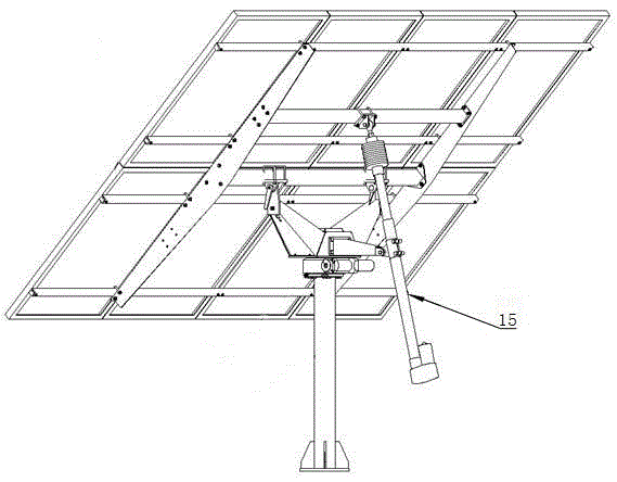
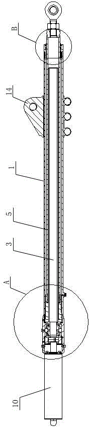
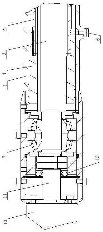
[0052] like figure 1 , 2 As shown, a linear drive device includes an outer tube 1 and a sealing end cap 2 arranged at the end of the outer tube 1, a mounting lug 14 is arranged on the outer tube, and a screw rod 3 is arranged in the outer tube 1, so The length-diameter ratio of the screw rod 3 is 20-25, one end of the screw rod 3 is connected with the driving mechanism, and a single row tapered roller bearing 7 is correspondingly arranged in the outer tube 1 and the connecting en...


PUM


Abstract

Disclosed are a linear drive apparatus and a method of controlling and using same for solar-energy tracking, the apparatus comprising an outer tube (1) and a sealing end cap (2) provided at the end of the outer tube (1), wherein a screw (3) is provided in the outer tube (1), one end of the screw (3) is connected to a drive mechanism, a drive nut (4) is provided on the ball screw (1) in a threaded fit therewith, an extension rod (5) is provided between the outer tube (1) and the screw (3), one end of the extension rod (5) is connected to the drive nut (4) and the other end thereof passes through the sealing end cap (2), a sealing assembly is provided between the extension rod (5) and the sealing end cap (2), and a waterproof and oil-proof ventilation stopper (6) is provided on the outer tube (1). The apparatus is mainly used on a solar-energy tracker, and corresponding structural designs from the point of view of flexural strength, load resistance and protection of the apparatus itself can be implemented according to the environment in which the solar-energy tracker is used, providing the present apparatus with reliable and stable operation and strong flexural strength and load resistance capacities when applied in a solar tracker, thereby effectively increasing the tracking precision of the solar-energy tracker.

Description

technical field [0001] The invention belongs to the technical field of solar energy tracking, and in particular relates to a linear drive device for a solar energy tracker and a control and use method thereof. Background technique [0002] like figure 1 As shown, it is the specific application of the existing linear drive device 15 in the solar tracker, which is mainly used for the solar dual-axis tracker's elevation angle (and also azimuth angle) tracking drive and the single-axis tracker drive. The existing linear drive devices mainly have the following problems: [0003] 1. When designing the solar tracker (dual-axis and single-axis), the center of gravity of the moving parts is designed to coincide with (close to) the rotating axis, thereby reducing the driving torque required for tracking and thus meeting the requirements of the tracker’s low energy consumption. In practical engineering applications, due to the special structural limitations of the tracker, this type ...

Claims


Application Information

Patent Timeline
Patent Type & Authority Patents(China)
IPC IPC(8): G05D3/12F24S50/20
CPCF16H25/20F24S50/20F24S2030/11Y02E10/47Y02E10/50Y10T74/1868Y10T74/18712F16H25/2418F16H2025/204F16H2025/2087H02S20/32H02S40/30
Inventor 黄忠
Owner CHENGDU ZSUN SCI & TECH DEVING
Why Eureka
Try Eureka