
Framework for optical fiber gyroscope and manufacturing method thereof as well as method for packaging optical fiber ring

A technology of fiber optic gyroscope and fiber optic ring, which is applied in the field of packaging fiber optic rings, can solve the problems of phase noise generated by optical receiving devices, achieve the effects of reducing sound pressure interference, avoiding heat flow direction, and eliminating stress and size effects

Active Publication Date: 2013-03-13
武汉华中天勤防务技术有限公司
View PDF5 Cites 29 Cited by
  • Summary
  • Abstract
  • Description
  • Claims
  • Application Information

AI Technical Summary

Problems solved by technology

Stress changes will cause changes in the fiber propagation constant and fiber size, which will cause phase noise in the optical receiving device

Method used


Image

  • Framework for optical fiber gyroscope and manufacturing method thereof as well as method for packaging optical fiber ring
  • Framework for optical fiber gyroscope and manufacturing method thereof as well as method for packaging optical fiber ring
  • Framework for optical fiber gyroscope and manufacturing method thereof as well as method for packaging optical fiber ring

Examples


Embodiment Construction

[0025] The present invention is further described as follows in conjunction with accompanying drawing and example:

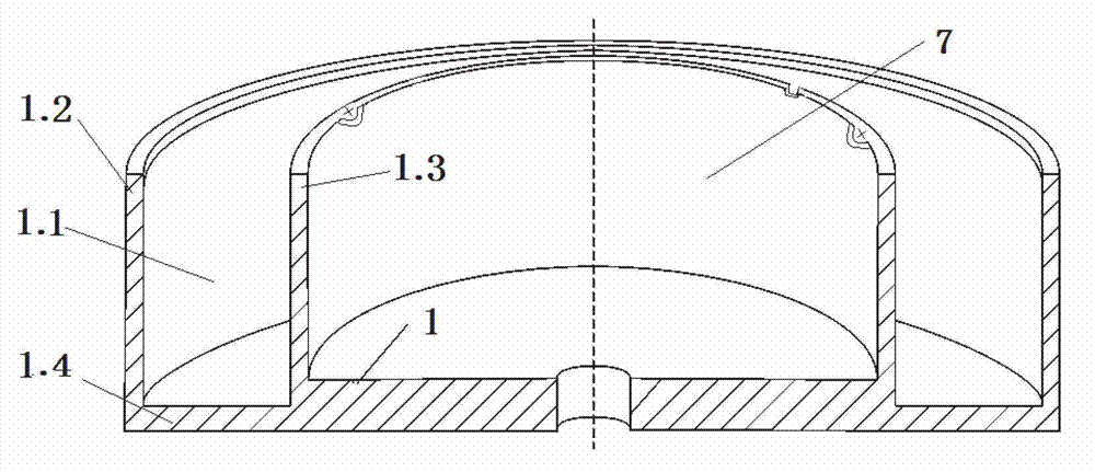
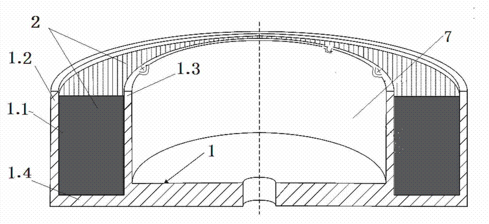
[0026] Such as figure 2 Shown in -7 is an embodiment of the skeleton for the fiber optic gyroscope of the present invention, which is a skeleton for the fiber optic gyroscope capable of heat and vibration isolation, including a skeleton body 1 composed of an outer wall 1.2, an inner wall 1.3 and a groove bottom 1.4; The annular groove 1.1 formed by the outer wall 1.2, the inner wall 1.3 and the groove bottom 1.4 is an open cavity for installing the optical fiber ring 6; the inner surface and the bottom surface of the annular groove 1.1 have a flame-retardant, heat-insulating and vibration-isolating material layer 2. There is an adhesive layer 3 on the thermal insulation and vibration isolation material layer 2; there is also a lower anti-vibration gasket 4.1 on the adhesive layer 3 on the bottom of the groove 1.4; the upper opening of the annular groove 1.1 is ...


PUM

PropertyMeasurementUnit
Thicknessaaaaaaaaaa
Thicknessaaaaaaaaaa
Thicknessaaaaaaaaaa

Abstract

The invention relates to a heat-insulating and vibration-proof framework for an optical fiber gyroscope and a manufacturing method thereof as well as a method for packaging an optical fiber ring. The framework for the optical fiber gyroscope comprises a framework body consisting of an outer wall, an inner wall and a groove bottom; an annular groove is an opening cavity used for mounting the optical fiber ring; the inner side surface and the bottom surface of the annular groove are provided with flame-retardant and heat-insulating and vibration-proof material layers; the material layers are coated with adhesive layers; the adhesive layer at the groove bottom is provided with a lower vibration-proof gasket; an upper vibration-proof gasket is further arranged at the opening at the upper part of the annular groove; the end face of the opening of the annular groove is provided with an optical fiber gyroscope top cover. The manufacturing method comprises the steps of: manufacturing the framework body; processing the flame-retardant and heat-insulating and vibration-proof material layers; coating the adhesive layers and paving the vibration-proof gaskets. The framework for the optical fiber gyroscope has the advantages that the environment temperature and the vibration influence are avoided, framework deformation and a series of errors of the optical fiber gyroscope caused by contact thermal conduction are also avoided, the environment adaptability of the gyroscope is improved, the service life is prolonged; the framework manufacturing method and the method for packaging the optical fiber ring are easy to operate, low in cost, high in efficiency, and stable and reliable in quality.

Description

technical field [0001] The invention relates to a skeleton for a fiber optic gyroscope capable of heat and vibration insulation, a manufacturing method thereof, and a method for encapsulating an optical fiber ring, in particular to a heat-insulation and vibration-isolation skeleton for a medium-to-high-precision fiber optic gyroscope used in a marine attitude or inertial navigation system and Its manufacturing method and packaging optical fiber ring method. Background technique [0002] The fiber optic gyroscope is a device for measuring the angular rate of the carrier relative to the inertial space. It eliminates the disadvantages of the traditional mechanical gyroscope and laser gyroscope. Widely used in navigation, aviation, aerospace, oil exploration and other fields. As a new generation of important inertial measurement devices, medium and low-precision fiber optic gyroscopes have been mass-produced and widely used. However, in medium and high-precision applications s...

Claims


Application Information

Patent Timeline
IPC IPC(8): G01C19/72
Inventor 张琛王四林朱牡丹
Owner 武汉华中天勤防务技术有限公司
Learn More