Distributing frame

A distribution frame and wire trough technology, applied in the field of distribution frame, can solve the problems of easy formation of knots, damage of wires, intertwining of wires, etc., and achieve the effects of low manufacturing cost, easy management, and simple and compact structure.

Active Publication Date: 2013-03-13
STATE GRID SHANDONG ELECTRIC POWER +1
View PDF8 Cites 4 Cited by
  • Summary
  • Abstract
  • Description
  • Claims
  • Application Information

AI Technical Summary

Problems solved by technology

In the current distribution frame, during the line arrangement process, the coiling operation is operated separately, and the coiled wires are piled up in the distribution frame, which is easy to cause confusion; when the wires are going out, the piled up wires are easy to form knots and intertwined, making it difficult to go out. Inconvenient operation, once the force is not uniform, it will cause damage to the wire, causing leakage, short circuit and other dangers

Method used


Image

  • Distributing frame
  • Distributing frame
  • Distributing frame

Examples


Embodiment Construction

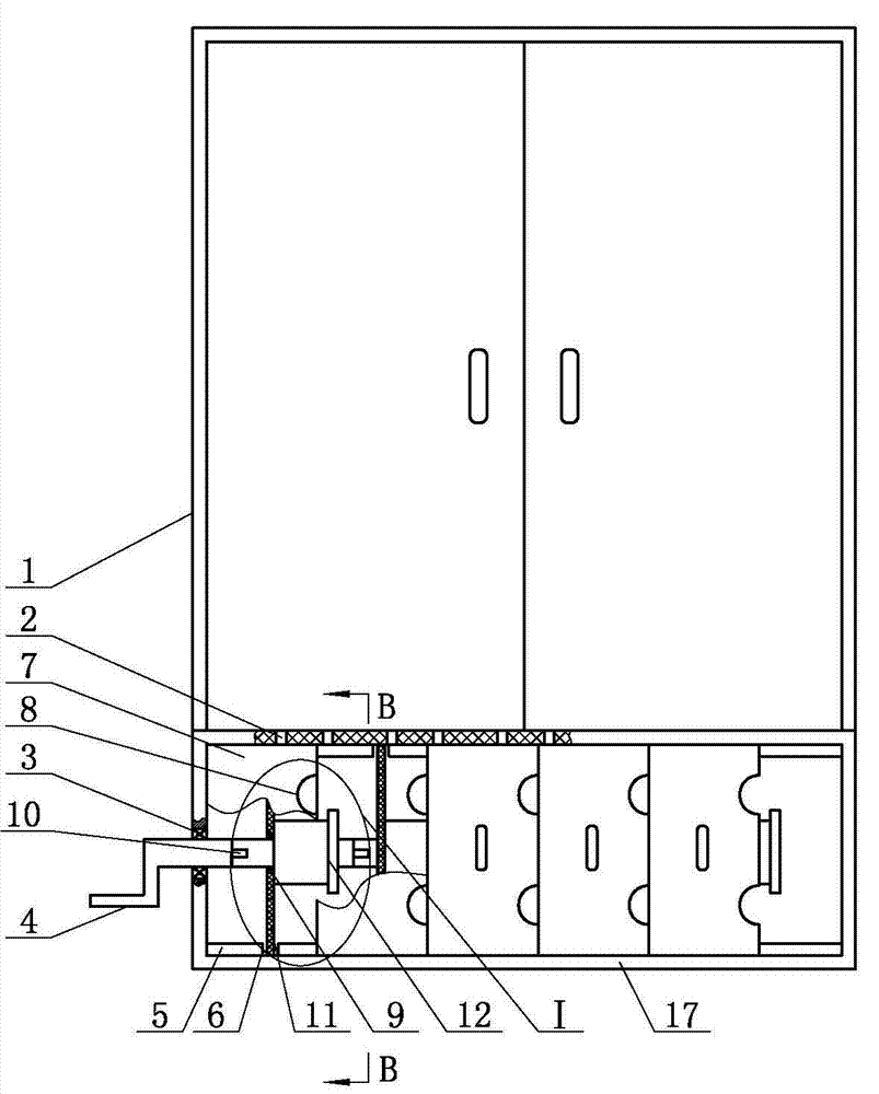
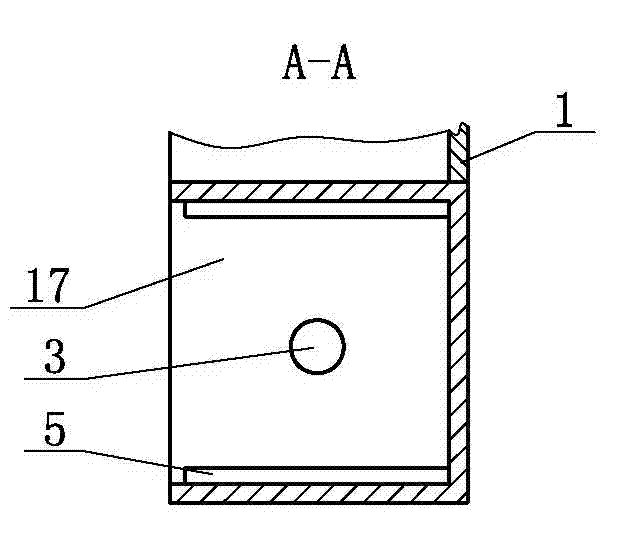
[0009] patch panels, such as figure 1 As shown, it includes a trunking box 17 with side openings, such as figure 2 and image 3 As shown, the top and the bottom in the wire trunking box 17 are provided with connecting frames 5, and several locking slots 6 are provided on each connecting frame 5, and the distance between each locking slot 6 is the same. Corresponding to the slot 6 provided on the connecting frame 6 at the bottom, the connecting plate 11 is inserted in the locking slot 6, and the line roller 12 is set on each connecting plate 11, as Figure 4 As shown, the spool of the wire roller 12 is connected with the connecting plate 11 by the first bearing 9, the first connecting shaft 13 is arranged at one end of the central axis of the wire roller 12, the second connecting shaft 15 is arranged at the other end of the central axis of the wire roller 12, and the second connecting shaft 15 is arranged at the other end of the central axis of the wire roller 12 The first p...


PUM


Abstract

The invention relates to a distributing frame which comprises a wire chase tank, wherein an opening is formed in the side edge of the wire chase tank, connecting frames are arranged in the wire chase tank, clamping grooves are formed in each connecting frame, connecting plates are spliced in the clamping grooves, a wire roller is arranged on each connecting plate, a spool of the wire roller is connected with the connecting plate through a first bearing, a first connecting shaft is arranged at one end of a central shaft of the wire roller, a second connecting shaft is arranged at the other end of the central shaft of the wire roller, a first lug is installed on the first connecting shaft, a groove with the same shape as the first lug is formed in the second connecting shaft, a rocking handle is arranged at an end part of the wire chase tank, a horizontal rod of the rocking handle is matched with the wire chase tank through a second bearing, and a second lug with the same shape as the first lug is arranged at an end part of the horizontal rod of the rocking handle. The distributing frame is provided with the independent wire rollers; the wires on the wire rollers are orderly arranged in the distributing frame, so as to be convenient for management; as the wires can be rotatably coiled or uncoiled simultaneously / independently between every two wire rollers, the operation is convenient; and the wires are evenly arranged when uncoiled, so as to avoid the electricity leakage, short circuit and other dangers due to the damaged wires and ensure the normal electrical work.

Description

technical field [0001] The invention relates to a power system device, specifically a distribution frame. Background technique [0002] The distribution frame is an important device for the line management of the power system. The distribution frame can organize various complex wires in an orderly manner to facilitate line management. In the current distribution frame, during the line arrangement process, the coiling operation is operated separately, and the coiled wires are piled up in the distribution frame, which is easy to cause confusion; when the wires are going out, the piled up wires are easy to form knots and intertwined, making it difficult to go out. It is inconvenient to operate, and once the force is uneven, it will cause damage to the wires, causing dangers such as leakage and short circuit. Contents of the invention [0003] In order to overcome the deficiencies in the prior art above, the present invention provides a distribution frame. [0004] In order...

Claims


Application Information

Patent Timeline
Patent Type & Authority Applications(China)
IPC IPC(8): B65H75/38B65H75/44
Inventor 卢志海王震冯迎春苏雷于强李守金张民孙兆国孟令国杨晓滨张天河李颖慧
Owner STATE GRID SHANDONG ELECTRIC POWER
Why Eureka
Try Eureka