


Quick Research
Generate reliable direction feasibility study reports for your R&D in just a few steps.

Technical Q&A
Discover and master advanced knowledge NOW. Basics, ideas, possibilities, all at once.

Find Solutions
As an expert in R&D theories, this can generate solutions to your technical problems instantly.

Evaluate Feasibility
Analyze your overall solution with one click, know your potential R&D risks in advance.

Monitor Landscape
Get weekly tech updates, stay abreast of the latest tech innovations and key insights.
Operating method for heat pump, and heat pump system
An operation method and technology of a heat pump system, which are applied to heating systems, heating methods, and central heating, can solve problems such as system instability, and achieve the effect of reducing reverse flow power.
- Summary
- Abstract
- Description
- Claims
- Application Information
AI Technical Summary
Problems solved by technology
Method used
Image

Examples
Embodiment approach 1
[0084] Hereinafter, embodiments of the present invention will be described with reference to the drawings. In addition, the embodiment described below is all for showing a specific example of this invention. Numerical values, shapes, materials, constituent elements, arrangement positions and connection forms of constituent elements, steps, order of steps, etc. shown in the following embodiments are merely examples, and are not intended to limit the present invention. In addition, among the constituent elements of the following embodiments, constituent elements not described in the independent claims showing the highest concept are described as arbitrary constituent elements.
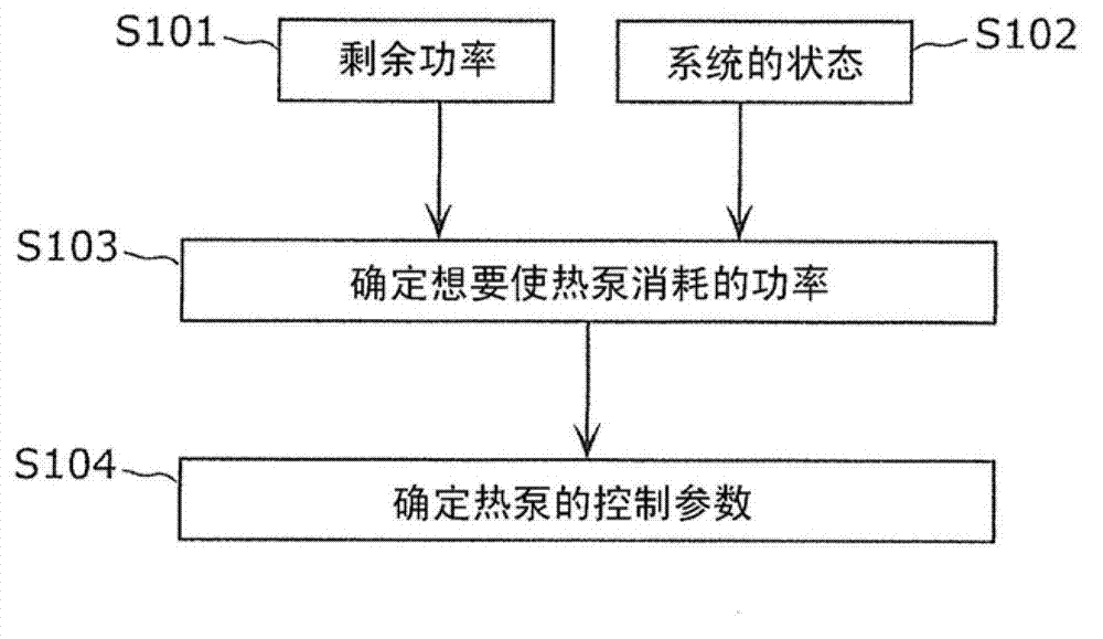
[0085] first, figure 1 It is a flowchart showing the outline of processing in the heat pump hot water supply system according to Embodiment 1 of the present invention.
[0086] Such as figure 1 As shown, the heat pump hot water supply system according to Embodiment 1 of the present invention first obt...
Embodiment approach 2
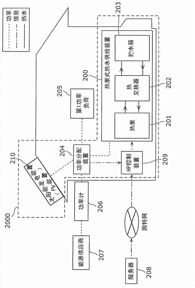
[0202] Next, heat pump hot water supply system 3000 according to Embodiment 2 of the present invention will be described. In Embodiment 1 described above, the HP control device 209 acquires the state of the local system from the server 208, and selects an operation method corresponding to the state of the system. However, such control cannot be performed in areas where the energy supplier 207 does not transmit information to the server 208 . In this case, in the present embodiment, it is possible to effectively reduce the amount of power flowing backward to the system and to suppress electricity charges.
[0203] Figure 21 It is a structural diagram explaining the heat pump type hot water supply system 3000 provided with the power generation device of this embodiment. Figure 21 and figure 2 The difference is that the HP control device 309 is not connected to the server 208 . Therefore, for figure 2 The same constituent elements are denoted by the same reference numera...
PUM
 Abstract
Description
Claims
Application Information
 - R&D Engineer
- R&D Manager
- IP Professional
- Industry Leading Data Capabilities
- Powerful AI technology
- Patent DNA Extraction
Browse by: Latest US Patents, China's latest patents, Technical Efficacy Thesaurus, Application Domain, Technology Topic, Popular Technical Reports.
© 2024 PatSnap. All rights reserved.Legal|Privacy policy|Modern Slavery Act Transparency Statement|Sitemap|About US| Contact US: help@patsnap.com