Semiconductor device
A semiconductor and device technology, applied in the field of semiconductor devices, can solve the problem of increasing power consumption of driving circuits, and achieve the effects of suppressing changes in power supply voltage, improving jitter characteristics, and suppressing changes
- Summary
- Abstract
- Description
- Claims
- Application Information
AI Technical Summary
Problems solved by technology
Method used
Image
Examples
no. 1 example
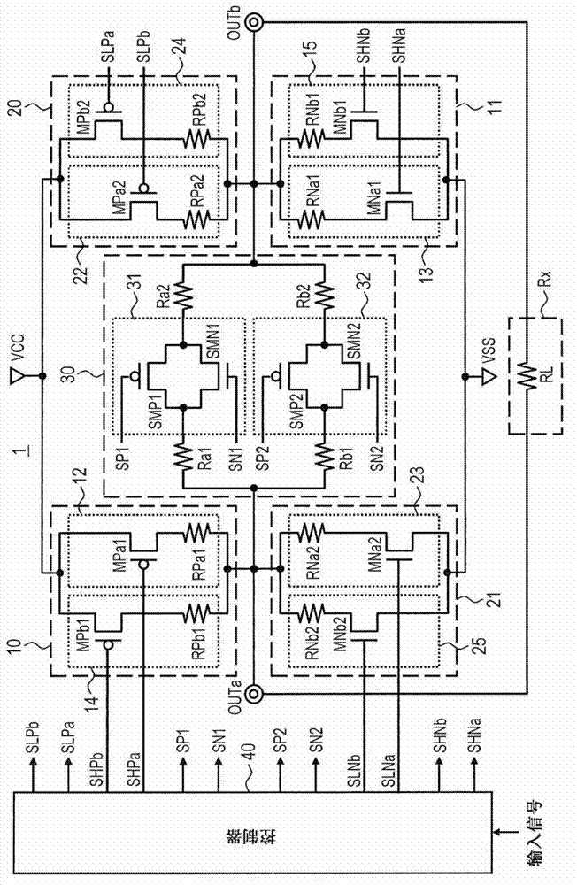
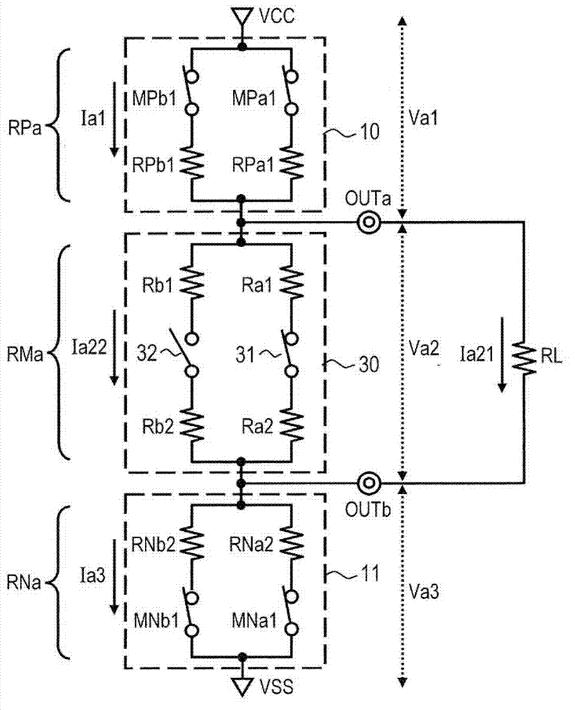
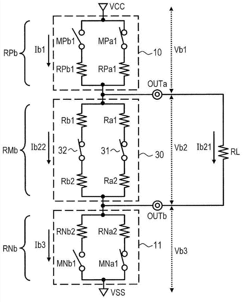
[0026] Embodiments of the present invention will be described below with reference to the drawings. figure 1 A block diagram of the semiconductor device 1 according to the first embodiment is shown. figure 1 A driving circuit and a controller for controlling the driving circuit in which the present invention focuses on the semiconductor device are shown. That is, the semiconductor device 1 includes many circuits that are not shown except the driving circuit. Such as figure 1 As shown in , the semiconductor device 1 includes a first driver 10 , a second driver 11 , a third driver 20 , a fourth driver 21 , a variable resistor 30 and a controller 40 . The semiconductor device 1 also includes a first output terminal OUTa and a second output terminal OUTb. The semiconductor device 1 outputs a differential signal having an amplitude corresponding to the input signal through the first output terminal OUTa and the second output terminal OUTb. The differential signal is transmitted...
no. 2 example
[0103] Figure 6 A block diagram of a semiconductor device 2 according to the second embodiment is shown in . In the semiconductor device 1 according to the first embodiment, each of the plurality of drivers has a resistor for determining the output impedance in the on state. However, if Figure 6 As shown in , in the semiconductor device 2 according to the second embodiment, a pair of resistors is shared by two drivers.
[0104] Accordingly, the semiconductor device 2 includes the first driver 50 , the second driver 51 , the third driver 60 and the fourth driver 61 in other configurations such as the first driver 10 , the second driver 11 , the third driver 20 and the fourth driver 21 .
[0105] The first driver 50 includes a first output setting unit 52 and a second output setting unit 54 . Furthermore, the fourth driver 61 includes a seventh output setting unit 63 and an eighth output setting unit 65 .
[0106] The first output setting unit 52 includes a first switching...
no. 3 example
[0122] Figure 7 A block diagram of a semiconductor device 3 according to the third embodiment is shown in . In the first and second embodiments, activation of the driver is operated by switching the transistor between on and off. The resistance value used to determine the magnitude of the differential signal is determined by the resistive element. On the other hand, in the third embodiment, the activation state of each driver is controlled by means of the on-resistance of the transistor. The magnitude of the differential signal is determined based on the on-resistance of the activated transistors.
[0123] Such as Figure 7 As shown in , the semiconductor device 3 includes a first driver 70 , a second driver 71 , a third driver 80 , a fourth driver 81 , a regulator circuit 33 , a variable resistor 34 , a controller 41 and a control voltage generator 42 . A regulator circuit 33 is provided in the semiconductor device 3 . The regulator circuit 33 outputs the same voltage a...
PUM
 Abstract
Description
Claims
Application Information
 - R&D
- Intellectual Property
- Life Sciences
- Materials
- Tech Scout
- Unparalleled Data Quality
- Higher Quality Content
- 60% Fewer Hallucinations
Browse by: Latest US Patents, China's latest patents, Technical Efficacy Thesaurus, Application Domain, Technology Topic, Popular Technical Reports.
© 2025 PatSnap. All rights reserved.Legal|Privacy policy|Modern Slavery Act Transparency Statement|Sitemap|About US| Contact US: help@patsnap.com


