Optical disc apparatus and method of setting defocus value thereof

Inactive Publication Date: 2008-02-14
SANYO ELECTRIC CO LTD
View PDF1 Cites 0 Cited by
  • Summary
  • Abstract
  • Description
  • Claims
  • Application Information

AI Technical Summary

Benefits of technology

[0032]By the above configuration, when the optical disc of good jitter characteristics is used, the defocus value is speedily set, and the optical pickup unit making up the optical disc apparatus performs the stabilized focus servo operation relative to the optical disc. The optical disc with which the value of the difference between the maximum jitter value and the minimum jitter value is smaller than the predetermined value is considered to be the optical disc of good jitter characteristics. Since the reference value of the defocus value is set in the optical disc apparatus as the optimum defocus value when the signal is read out from the optical disc of the good jitter characteristics, no problem is caused to the focus servo operation of the optical pickup unit and the stabilized focus servo operation is executed at the optical pickup unit.
[0034]The above configuration enables provision of the optical disc apparatus capable of setting the optimum defocus value.

Problems solved by technology

Conventional optical pickup units had the problem that due to the difference between individual pickup units themselves and the difference between individual optical discs, a focused focal point controlled by the focus point and the focus servo operation was not performed in optimum condition.
However, in this optical disc reading unit, it is feared, for example, that since the focus bias volume is set by arithmetic processing, a long time is required for setting processing.
When a method of setting the focus bias volume based on the minimum value of the jitter value is employed, the following problem is feared.
When the focus bias volume was set as above, there was a problem that the focus servo operation became unstabilized.
When the defocus value is set to meet the optimum jitter with respect to such optical discs, such defocus value makes the servo unstable and causes a loss of focus or so-called F loss, etc. to take place.
The loss of focus means, for example, that a focal point of the laser light irradiated from the optical pickup unit is caused to deviate relative to pits of the disc being tracked and thereby the data stored on the disc becomes unreadable.

Method used


Image

  • Optical disc apparatus and method of setting defocus value thereof
  • Optical disc apparatus and method of setting defocus value thereof
  • Optical disc apparatus and method of setting defocus value thereof

Examples


Embodiment Construction

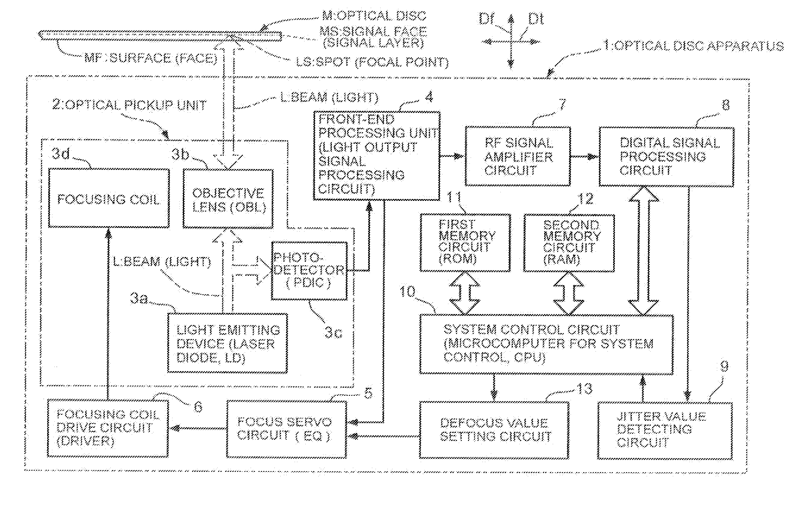
[0041]Detailed description will then be made of an embodiment of an optical disc apparatus and a defocus value setting method thereof according to the present invention.

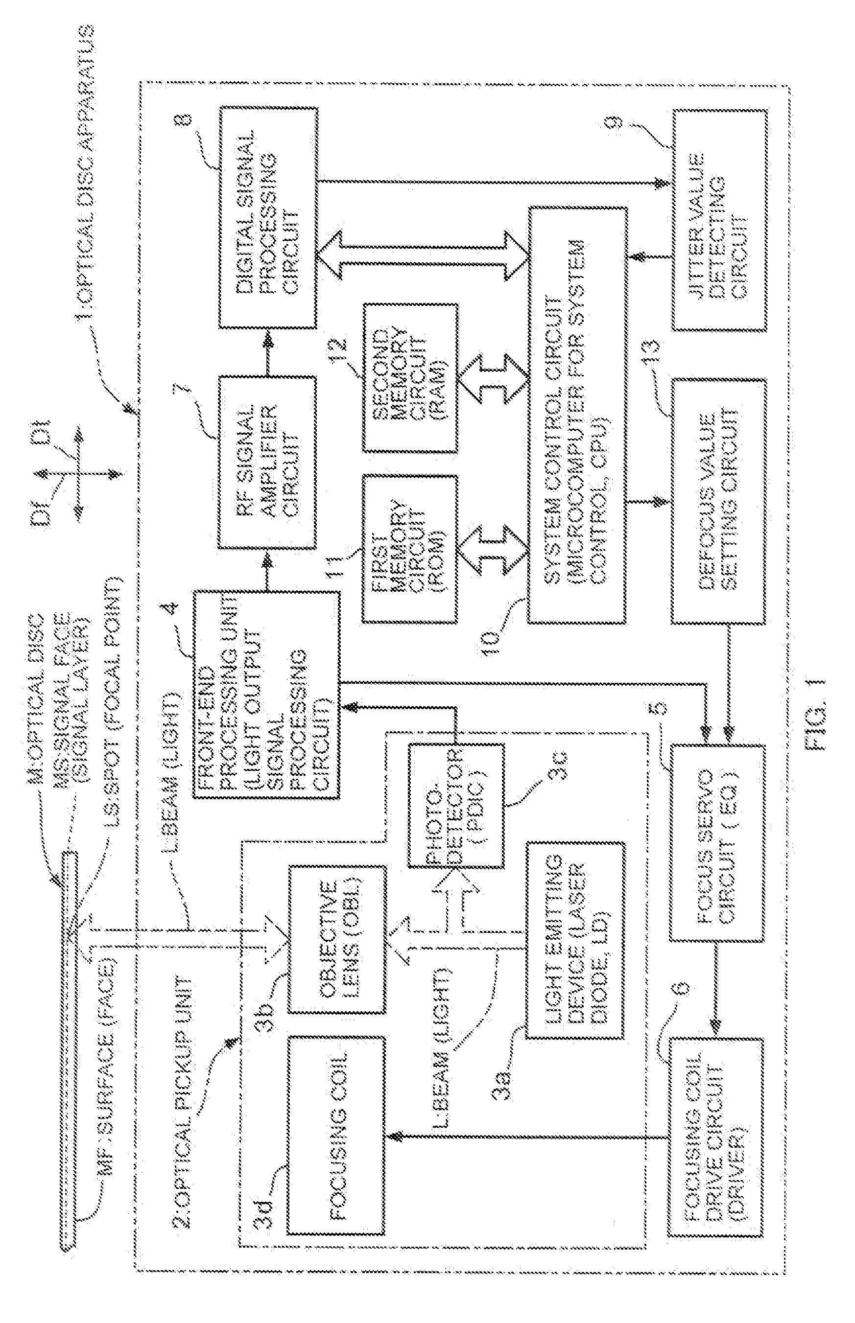
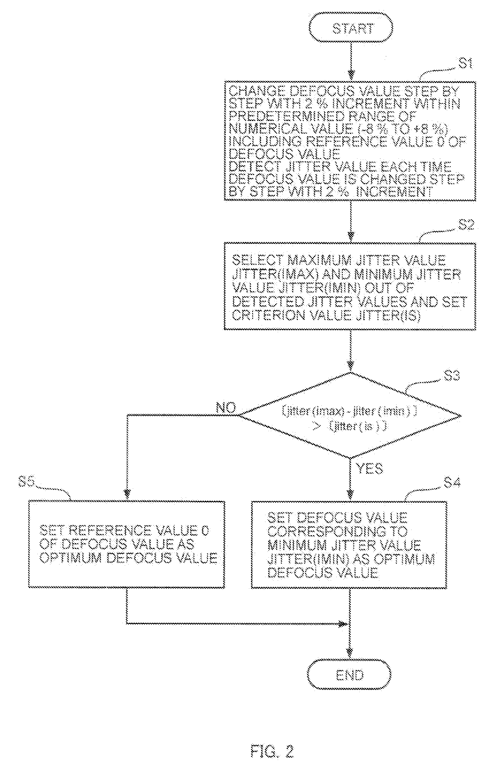
[0042]FIG. 1 is a block diagram of an embodiment of the optical disc apparatus according to the present invention, FIG. 2 is a flow chart of an embodiment of the defocus value setting method of the optical disc apparatus according to the present invention, FIG. 3 is a graph of relationship between a defocus value and a jitter value, and FIG. 4 is also a graph of the relationship between the defocus value and the jitter value.

[0043]The optical disc apparatus 1 shown in FIG. 1 is configured to be capable of setting the defocus value suitable for performing a focus servo movement, using the jitter value of a signal obtained from an optical disc N. As described above, the jitter means a subtle vibration or distortion of the signal. The focus means a focal point or a focal point of lens. The servo means a mechanism, etc.,...


PUM


Abstract

An optical disc apparatus is disclosed that comprises a jitter value detecting circuit that detects a jitter value based on the signal read out from an optical disc; and a defocus value setting circuit that adjusts a defocus value used for moving an objective lens along the direction of a light axis when focusing of the objective lens to the optical disc is performed, based on the signal that has gone through the jitter value detecting circuit, and causes a defocus adjustment to be made based on the defocus value.

Description

CROSS-REFERENCE TO RELATED APPLICATIONS[0001]This application claims the benefit of priority to Japanese Patent Application No. 2006-157220, filed Jun. 6, 2006, of which full contents are incorporated herein by reference.BACKGROUND OF THE INVENTION[0002]1. Field of the Invention[0003]The present invention relates to an optical disc apparatus and a defocus value setting method thereof, capable of recording a signal on an optical disc by laser light irradiated by an optical pickup unit and reproducing the signal recorded on the optical disc by the laser light.[0004]2. Description of the Related Art[0005]Laser light irradiated by an optical pickup unit (OPU) of an optical disc apparatus is focused on a signal face of an optical disc. Laser is an abbreviation of “light amplification by stimulated emission of radiation”. Various kinds of technology of focusing the laster light on the signal face of the optical disc or so-called focus control technology are available. Generally, focus con...

Claims


Application Information

Patent Timeline
IPC IPC(8): G02B27/64
CPCG11B7/0945
Inventor MURAOKA, YASUHIROARAI, TATSUSHI
Owner SANYO ELECTRIC CO LTD
Why Eureka
Try Eureka