
Drive method of plasma display device

A plasma display and driving method technology, applied in static indicators, instruments, identification devices, etc., can solve the problems of interface image retention, cluttered charge distribution, and different wall charges, so as to reduce the generation of boundary afterimages, improve the Jitter characteristics, the effect of reducing variance

Inactive Publication Date: 2007-12-05
LG ELECTRONICS(NANJING) PLASMA CO LTD
View PDF0 Cites 0 Cited by
  • Summary
  • Abstract
  • Description
  • Claims
  • Application Information

AI Technical Summary

Problems solved by technology

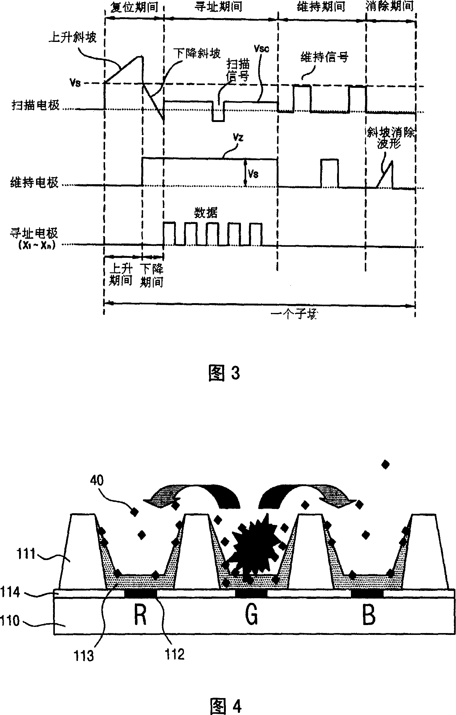
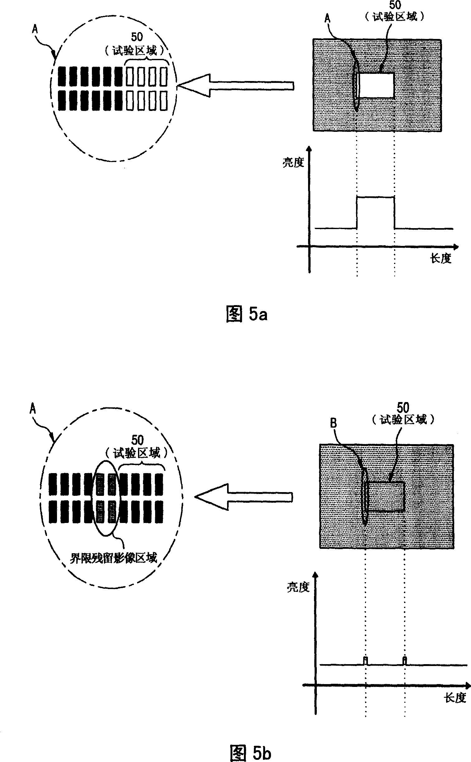
[0026] In summary, the driving waveform of the prior art plasma display driving method has the following problems: in the region between the discharge part and the non-discharge part of the plasma display, that is, the distribution of the wall charges in the boundary part of the discharge cell is disordered, which deteriorates the jitter characteristics ; In addition, the wall charge distribution among the discharge cells is uneven, that is, the quantity of the wall charge between the discharge cells is different from each other, and the image sticking phenomenon at the interface is serious.

Method used


Image

  • Drive method of plasma display device
  • Drive method of plasma display device
  • Drive method of plasma display device

Examples


Embodiment Construction

[0053] Hereinafter, the driving method of the plasma display of the present invention will be described in detail with reference to the accompanying drawings.

[0054] FIG. 8 is a schematic diagram of driving waveforms formed by the driving method of the plasma display according to the present invention. As shown in the figure, in the driving waveforms of the plasma display driving method according to the present invention, the reset period includes a rising period with a rising ramp (Ramp-up) waveform and a falling period with a falling ramp (Ramp-down) waveform. At this time, during the rising period, the surface discharge between the scan electrode and the sustain electrode and the opposite discharge between the scan electrode and the address electrode occur simultaneously, and the wall charge distribution in the discharge cell is uniform. In this way, not only the wall charges in the discharge cells can be evenly distributed in the respective discharge cells, but also the ...


PUM


Abstract

The invention discloses a driving method of plasma display to modify reset waveshape during rising period of reset stage, which is characterized by the following: reducing residual image; modifying shake property; utilizing at least one subfield combination to display image of address-searching electrode, scanning electrode and extra voltage of maintaining electrode during reset period, address-searching period and maintaining period; driving the reset period into rising period and falling period; proceeding at least one surface discharge between scanning electrode and maintaining electrode and at least one opposite direction discharge between scanning electrode and address-searching electrode during rising period.

Description

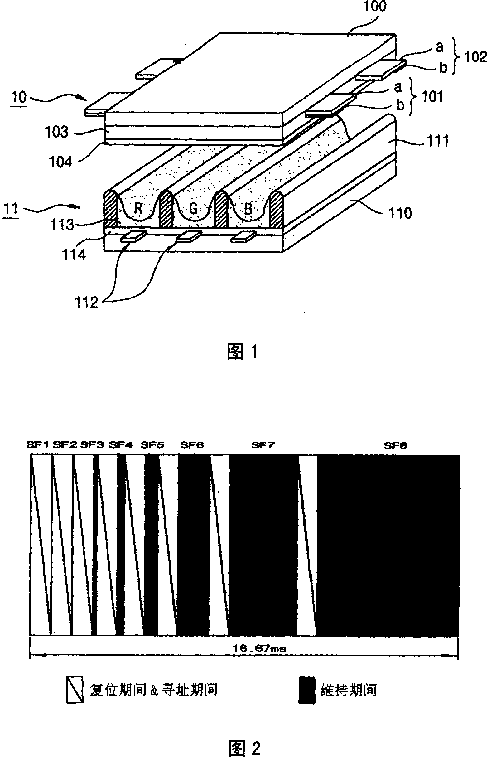
technical field [0001] The invention relates to a driving method of a plasma display, in particular to a driving method of a plasma display which reduces dark afterimages by applying a reset waveform during a reset period. Background technique [0002] Generally speaking, the partition wall between the front panel and the rear panel of the plasma display forms a unit cell, and each cell is filled with neon (Ne), helium (He), neon-helium (Ne+He) mixed gas or such discharge gas and An inert gas containing a small amount of xenon. When the high voltage is discharged, the inert gas emits vacuum ultraviolet rays (Vacuum Ultraviolet rays), which can make the phosphors in the partition walls emit light, thereby displaying images. Therefore, the plasma display is attracting attention as a next-generation iconic display with its thin and light construction. [0003] FIG. 1 is a schematic diagram of the structure of a general plasma display. As shown in the figure, a plurality of s...

Claims


Application Information

Patent Timeline
Patent Type & Authority Applications(China)
IPC IPC(8): G09G3/28G09G3/20H01J17/49G09F9/313G09G3/288
Inventor 李炳俊
Owner LG ELECTRONICS(NANJING) PLASMA CO LTD
Learn More