Wireless charge coil structure of electronic device

A technology of wireless charging and electronic devices, which is applied in the direction of circuit devices, coils, circuits, etc., can solve the problems of high price, inconvenient portability, and excessive volume, and achieve high magnetic permeability characteristics, stable power transmission, and control of electromagnetic wave dispersion. Effect

Active Publication Date: 2013-03-06
FU TONG TECH
View PDF3 Cites 17 Cited by
  • Summary
  • Abstract
  • Description
  • Claims
  • Application Information

AI Technical Summary

Problems solved by technology

[0010] Aiming at the deficiencies of the prior art, the purpose of the present invention is to provide a wireless charging coil structure for electronic de

Method used


Image

  • Wireless charge coil structure of electronic device
  • Wireless charge coil structure of electronic device
  • Wireless charge coil structure of electronic device

Examples


Embodiment Construction

[0036] In order to achieve the above objectives and effects, the technical means and structures adopted by the present invention are described in detail with respect to the preferred embodiments of the present invention and their features and functions are as follows, so as to facilitate complete understanding.

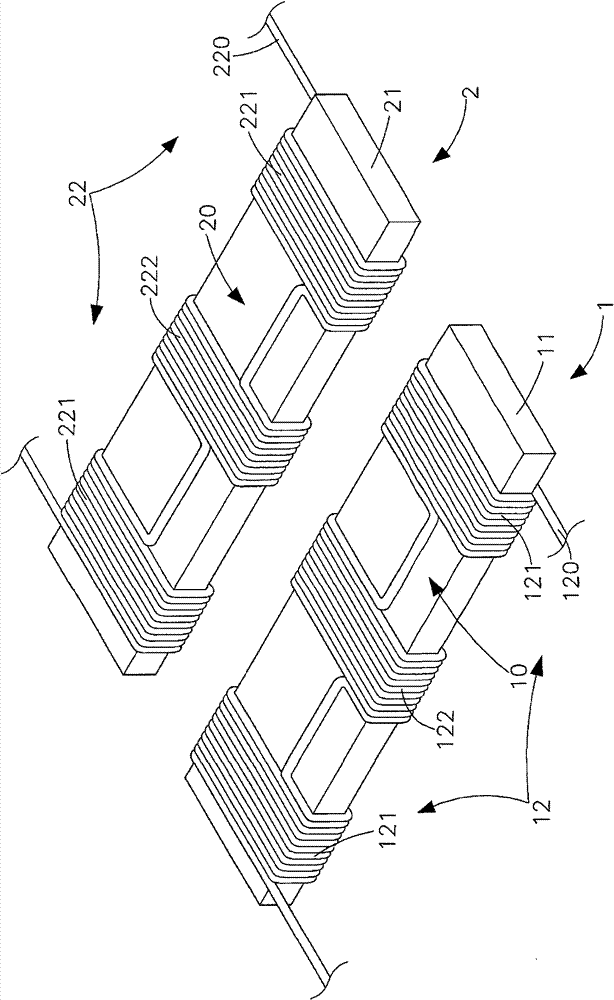
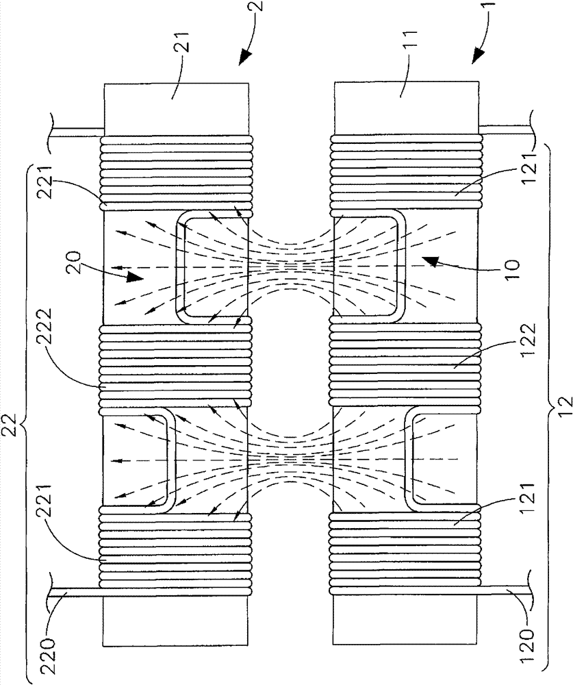
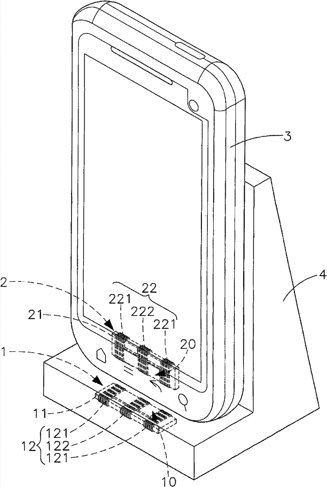
[0037] see figure 1 , figure 2 , image 3 , Figure 4 Shown are a three-dimensional appearance view, a schematic diagram of electromagnetic induction, a three-dimensional appearance diagram of a preferred embodiment and a three-dimensional appearance diagram of another preferred embodiment of the present invention. It can be clearly seen from the figures that the present invention includes a power supply coil module. 1 and the power receiving coil module 2, so the main components and features of this case are described in detail as follows, among which:

[0038] The power supply coil module 1 has a magnetic conductor 11 and an induction coil 12 , wherein the magn...


PUM


Abstract

The invention relates to a wireless charge coil structure of an electronic device. The wireless charge coil structure comprises a power supply coil module and a power receiving coil module, wherein the power supply coil module is capable of transmitting electromagnetic energy and the power receiving coil module is capable of inducing electromagnetic wave to receive electric energy. Each of the power supply coil module and the power receiving coil module is provided with an elongated magnetic conductor. An insulated wire is wound on the magnetic conductor to form a first coil. The first coil extends along the magnetic conductor to a preset length and is then reversely wound to form a second coil. Therefore, winding is sequentially performed to form an induction coil having at least two groups of the first coil and the second coil. Induction intervals with preset space between the first coil and the second coil magnetically induce to transmit signals and electric energy. The wireless charge coil structure is applicable to both planar handheld electronic devices and devices of wireless power transmission systems requiring narrow induction surfaces to transmit energy.

Description

technical field [0001] The invention relates to a wireless charging coil structure, in particular, a first coil is surrounded by an insulated wire on a magnetic conductor, and after the first coil is extended for a predetermined length, a second coil is formed in the reverse direction, and the first coil and the Electric power is induced in the induction area between the second coils, and this structure can be used in a device for transmitting energy with a narrow induction surface. Background technique [0002] The rapid development of today's electronic technology and multimedia information has made hand-held electronic devices such as notebook computers, tablet computers, smart phones, and personal digital assistants develop towards the trend of being light, thin, short, and multi-functional. And other characteristics, coupled with the continuous innovation of software and hardware functions, more practical effects in use, has become an indispensable part of people's work...

Claims


Application Information

Patent Timeline
IPC IPC(8): H02J17/00H01F5/00H02J50/12
Inventor 蔡明球詹其哲
Owner FU TONG TECH
Why Eureka
Try Eureka