
Device and method for testing performance of high-temperature pipeline heat insulation clad material

A technology of coating materials and testing devices, which is applied in the field of testing devices for the performance effect of heat insulation coating materials for high-temperature exhaust pipes of large ships, can solve the problems of large investment, one-sided test results, waste of manpower and materials, etc., and achieve the goal of measuring temperature High, easy to move and install, easy to operate

Inactive Publication Date: 2013-03-06
苏州市联东化工厂
View PDF4 Cites 10 Cited by
  • Summary
  • Abstract
  • Description
  • Claims
  • Application Information

AI Technical Summary

Problems solved by technology

In the case of field tests, the investment is huge, and it is difficult to clarify the technical boundaries, resulting in unnecessary waste of manpower and materials
[0003] Existing performance testing methods for pipeline insulation materials are mainly based on laboratory heat transfer oil pipes. The maximum temperature of heat transfer oil is 400°C. It is difficult to simulate high temperature pipelines above 500°C, and it is impossible to accurately evaluate the performance of heat insulation materials.
If the measurement temperature exceeds 500°C, large-scale pipeline equipment must be used, which is not convenient for test construction, long test period, reproducibility of simulated parts, poor reliability, and one-sided test results

Method used


Image

  • Device and method for testing performance of high-temperature pipeline heat insulation clad material
  • Device and method for testing performance of high-temperature pipeline heat insulation clad material
  • Device and method for testing performance of high-temperature pipeline heat insulation clad material

Examples


Embodiment Construction

[0014] The present invention will be further described below in conjunction with accompanying drawing:

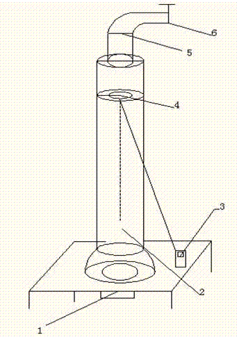
[0015] Such as figure 1 The present invention shown includes a combustion furnace (1). The hot air outlet of the combustion furnace is connected with a heating pipe (2). The telescopic cover sheet (6) for the air outlet flow rate, the inner wall and the outer wall of the heating tube are provided with temperature measuring points, and the temperature measuring points are also connected with thermocouple thermometers (3).

[0016] The heating device is a combustion furnace device, and the combustion furnace device is a natural gas furnace or a gas furnace or an acetylene gas furnace or other combustion heat source devices.

[0017] The heating pipes are cast iron pipes, wrought iron leather pipes or carbon steel pipes, and the heating pipes can be straight or straight with elbows or straight with branch pipes.

[0018] The heat flow discharge regulating pipe is a white iro...


PUM

PropertyMeasurementUnit
heightaaaaaaaaaa
thicknessaaaaaaaaaa
heightaaaaaaaaaa

Abstract

The invention discloses a device and a method for testing the performance of a high-temperature pipeline heat insulation clad material. The device comprises a combustion furnace, a heating pipe, a hot airflow discharge pipe, a thermocouple thermometer and an infrared thermometer, wherein the tested heat insulation material is sprayed or coated on a heating straight pipe; the combustion furnace serves as a heating source, the flame size can be adjusted, the hot airflow discharge is controlled, and the inner temperature is adjusted to a required testing temperature; the temperature of the inner pipe and the heat insulation outer surface is measured, comparative reference is formed, and the heat insulation performance is obtained; and meanwhile, the evaluation of mechanical strength of a heat insulation material on a similar high-temperature exhaust pipe part is simulated. The device has the advantages that 1. the measurable temperature is high, and the temperature can be controlled to be between 20 and 1200 DEG C; 2. the advantages of the heat insulation effect and the mechanical property can be intuitively given; and 3. a set of accurate and feasible device for testing and evaluating heat insulation property of the heat insulation material suitable for an exhaust pipe part of a large ship can be formed.

Description

technical field [0001] The invention relates to a heat insulation performance test device and a test method, in particular to a test device and a test method for the performance effect of heat insulation coating materials for high-temperature exhaust pipes of large ships. Background technique [0002] High-temperature heat-resistant insulation materials are extremely important in the insulation of high-temperature pipelines, especially the exhaust pipes of large-scale ship engines with a temperature exceeding 500°C. Their performance is directly related to the safety of the pipeline and its surrounding personnel, and the maintenance cycle And costs, environmental protection and many other issues. Especially in the high-temperature exhaust pipe parts with limited space and complicated appearance, the use of plastic heat insulation materials has great advantages. The required insulation material is not only good or bad in terms of cooling and heat insulation performance, but ...

Claims


Application Information

Patent Timeline
Patent Type & Authority Applications(China)
IPC IPC(8): G01N25/20
Inventor 刘明忠徐云龙刘毅
Owner 苏州市联东化工厂
Learn More