
Laser evaporation coating device

A coating device and laser evaporation technology, applied in vacuum evaporation coating, sputtering coating, ion implantation coating, etc., can solve the problems of low heating melting point, pollution of vacuum cavity, and inability to heat high melting point metal materials, etc., to achieve Effects of reduced pollution, high evaporation rate, and simple structure

Inactive Publication Date: 2013-03-06
ZHONGSHAN CHUANGKE RES TECH SERVICE
View PDF2 Cites 7 Cited by
  • Summary
  • Abstract
  • Description
  • Claims
  • Application Information

AI Technical Summary

Problems solved by technology

[0002] The traditional evaporation coating device uses contact heating, which will pollute the vacuum chamber
In addition, its heating melting point is low, and it is impossible to heat high melting point metal materials to evaporate them.

Method used


Image

  • Laser evaporation coating device

Examples


Embodiment Construction

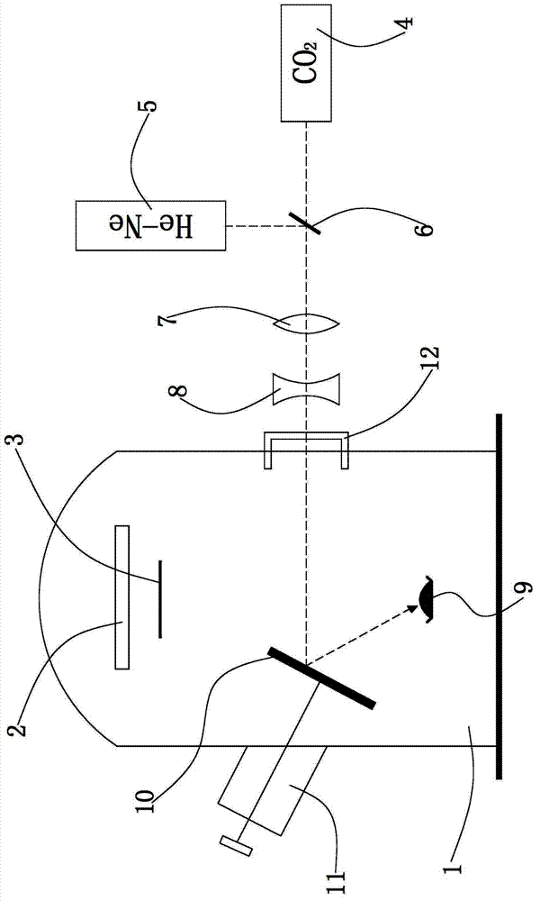
[0023] Such as figure 1 As shown, a laser evaporation coating device includes a vacuum reaction chamber 1, a substrate frame 2, an adjustable baffle 3, a CO 2 Laser 4 , a He-Ne laser 5 , a beam splitter 6 , a focusing convex lens 7 , a defocusing concave lens 8 , a pincer 9 , a mirror 10 , and a mirror adjustment device 11 .

[0024] The side wall of the vacuum reaction chamber 1 is sealed with a window 12 made of Ge or ZnSe material.

[0025] The substrate frame 2 is arranged in the vacuum reaction chamber 1 for placing the substrate or substrate to be coated.

[0026] The CO 2 The laser 4 is located outside the vacuum reaction chamber 1 and arranged horizontally, and its laser emits laterally and is opposite to the window 12 .

[0027] The He-Ne laser 5 is located outside the vacuum reaction chamber 1 and arranged vertically, and emits laser light longitudinally.

[0028] The beam splitter 6 is located outside the vacuum reaction chamber 1 and is located in the CO at an ...


PUM


Abstract

The invention relates to a laser evaporation coating device, which is characterized by comprising a vacuum reaction chamber, a substrate frame, a CO2 laser device, a He-Ne laser device, a beam splitter, a focusing convex lens, a defocusing concave lens, a crucible and a reflecting mirror, wherein the beam splitter is positioned outside the vacuum reaction chamber and is arranged in the intersected position of laser beams sent out by the CO2 laser device and the He-Ne laser device in an angle of 45 degrees; the crucible is used for containing materials to be evaporated; the reflecting mirror is positioned above the crucible and is used for reflecting the laser sent out by the laser device into the crucible after the laser sequentially passes through the beam splitter, the focusing convex lens, the defocusing concave lens and a window from outside to inside, and the materials to be evaporated in the crucible are heated and evaporated by the laser, so that a film layer containing the materials to be evaporated is deposited on the surface of a base material or substrate on the substrate frame through vapor deposition. The laser evaporation coating device disclosed by the invention has a simple structure, and can be used for heating high-melting metal materials in a non-contact mode to evaporate the materials so as to realize laser evaporation coating, and the body of the vacuum reaction chamber can not be polluted.

Description

Technical field: [0001] The invention relates to a laser evaporation coating device. Background technique: [0002] The traditional evaporation coating device uses contact heating, which will pollute the vacuum chamber. In addition, its heating melting point is low, and it is impossible to heat the high melting point metal material to evaporate it. Therefore, it is necessary to improve the existing technology to provide a laser evaporation coating device, which can realize non-contact heating without polluting the vacuum reaction chamber. Invention content: [0003] The object of the present invention is to provide a laser evaporation coating device, which has a simple structure, and can conduct non-contact heating to vaporize high-melting point metal materials to realize laser evaporation coating without polluting the vacuum reaction chamber. [0004] A laser evaporation coating device, characterized in that: comprising [0005] A vacuum reaction chamber, the side wall...

Claims


Application Information

Patent Timeline
Patent Type & Authority Applications(China)
IPC IPC(8): C23C14/28
Inventor 粟婷杨柳刘昕
Owner ZHONGSHAN CHUANGKE RES TECH SERVICE
Learn More