Eureka AIR delivers breakthrough ideas for toughest innovation challenges, trusted by R&D personnel around the world.

Block body for connecting cable protection pipe, and connecting structure of cable protection pipe

A technology for protecting tubes and connecting cables, which is used in cable installation, cable installation in cable rooms, and cable laying equipment. High, simple and reliable connection effect

Active Publication Date: 2013-02-27
RIKAWA PLASTIC +1
View PDF8 Cites 4 Cited by
  • Summary
  • Abstract
  • Description
  • Claims
  • Application Information

AI Technical Summary

Problems solved by technology

However, in the case of this screw-in type, it is usually necessary to rotate the heavy block or the elongated cable protection tube while performing the above-mentioned screwing, and there is still a problem that the connection work of the cable protection tube to the block becomes difficult. Trouble with such a bad situation
Especially in the actual field construction, most of the cases are to connect multiple cable protection tubes to multiple blocks installed on the side wall of the hand hole, so in the screw-in type connection, there is a significant change in construction. such a bad situation

Method used


Image

  • Block body for connecting cable protection pipe, and connecting structure of cable protection pipe
  • Block body for connecting cable protection pipe, and connecting structure of cable protection pipe
  • Block body for connecting cable protection pipe, and connecting structure of cable protection pipe

Examples


Embodiment Construction

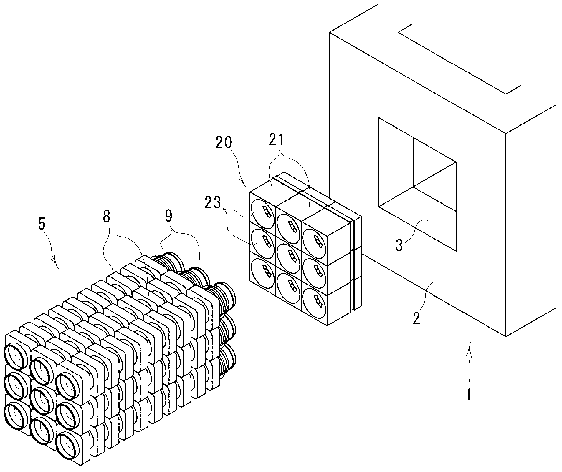
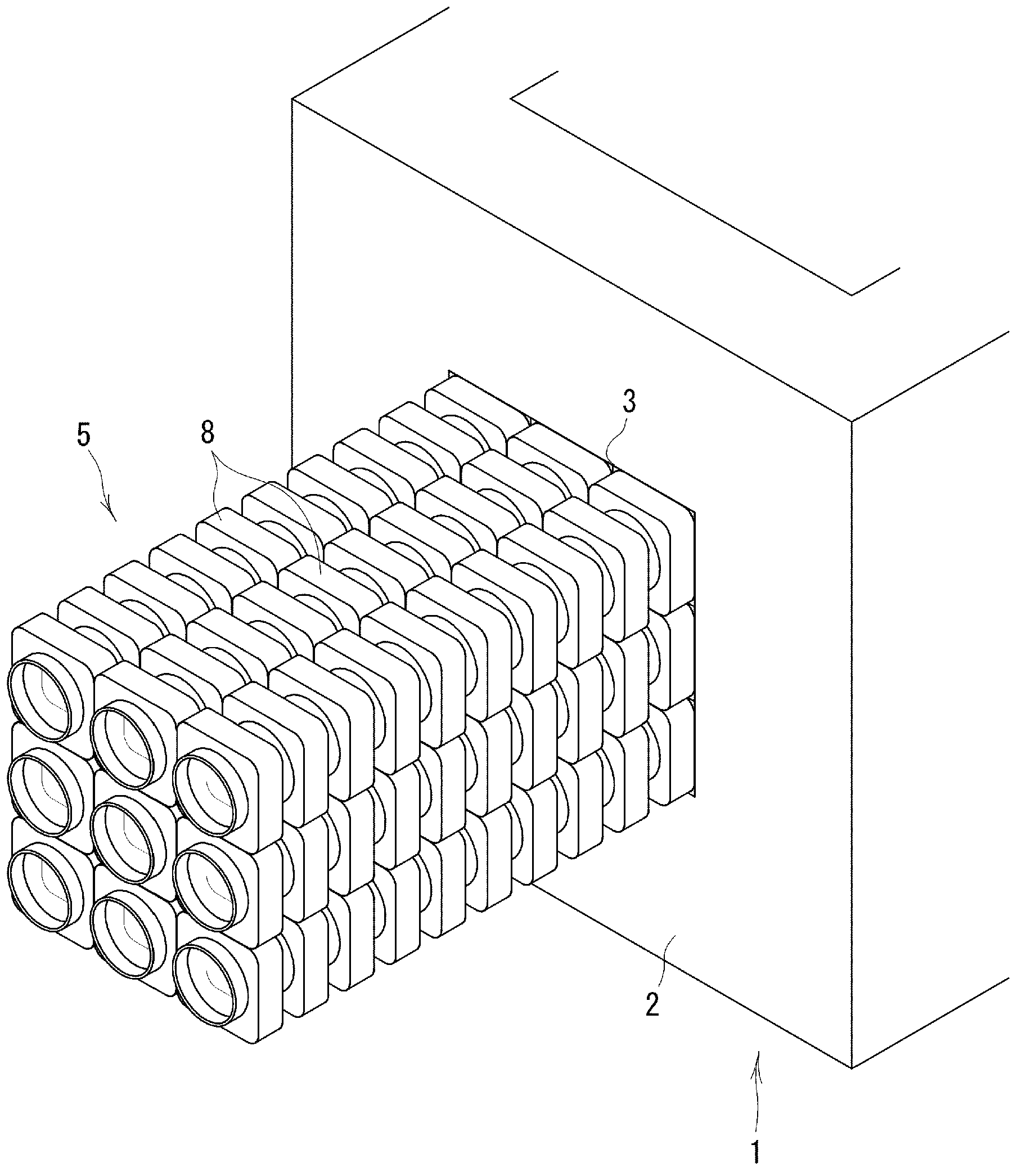
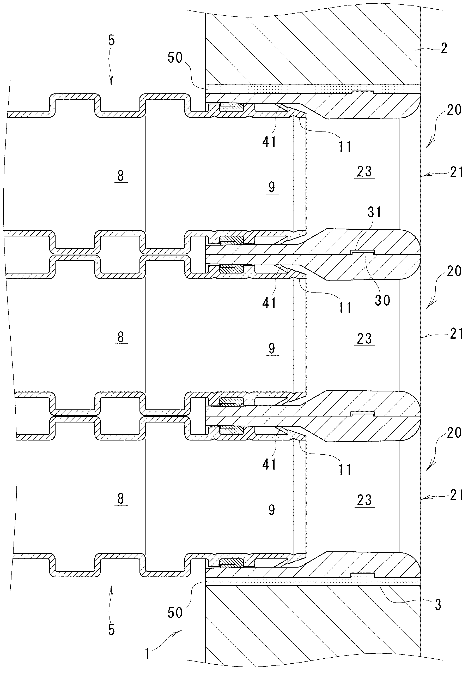
[0045] Hereinafter, embodiments of the present invention will be described in detail based on the drawings. Figure 1 to Figure 3 The connection structure of the cable protection tube which concerns on one Embodiment of this invention is shown. In the figure, 1 is a hand hole (including a man hole) made of concrete or resin concrete, and a square-shaped through-hole portion 3 is formed on the side wall 2 thereof.

[0046] Reference numeral 5 denotes a synthetic resin cable protection tube formed, for example, by blow molding, which is embedded in the ground and cables such as electric wires and optical fiber cables are inserted therein. Such as Figure 4 and Figure 5 As shown, the cable protection tube 5 has a tube wall 8, and the tube wall 8 alternately has protrusions 6 with a tube radial section in a substantially square shape along the tube axial direction and a tube radial section with a roughly square shape. Circular recess 7 . . . Furthermore, a male adapter 9 is i...


PUM


Abstract

Disclosed is a block body that is to be installed onto a side wall of a hand hole, and to which cable protection pipes are to be connected, wherein connecting work of the cable protection pipes can be conducted with ease and reliability. The block body (20) is provided with resin-concrete block main-bodies (21) each of which has a insertion-mounting hole section (23), and a plurality of synthetic-resin coming-off prevention members (22). Each of the coming-off prevention members (22) is comprised of an anchoring piece (40) buried within the block main-body (21); and a latching piece (41) that juts out into the insertion-mounting hole section (23), and has elasticity in the diameter direction of the insertion-mounting hole section (23). Insertion of a cable protection pipe (5) into the insertion-mounting hole section (23) is allowed, by pushing a latching projecting section (11) of the cable protection pipe (5) onto the insertion-mounting hole section (23), which thereby pushes and widens the latching pieces (41) in the outer direction of the diameter of the insertion-mounting hole section (23). The elastically returned latching pieces (41) are thereby latched to the latching projecting section (11) of the cable protection pipe (5) that was inserted into the insertion-mounting hole section (23), preventing the cable protection pipe (5) from coming off of the insertion-mounting hole section (23).

Description

technical field [0001] The present invention relates to a block body installed on the side wall of a hand hole or a manhole for connecting a cable protection pipe buried in the ground, and a connection structure of a cable protection pipe using the block body. Background technique [0002] Conventionally, the underground burying of cables such as electric wires and optical fiber cables has been promoted for the purpose of improving the cityscape and the like. In this case, the cables are protected by inserting them into a cable protection pipe buried in the ground. Furthermore, the cable protection tube is connected to hand holes or manholes provided at appropriate intervals, and in the hand holes or manholes (hereinafter, two holes are represented and simply referred to as "hand holes"), Relay, removal, maintenance, etc. of cables. [0003] When connecting the cable protection tube to the hand hole, for example, in most cases, a concrete block with a synthetic resin bell ...

Claims


Application Information

Patent Timeline
Patent Type & Authority Applications(China)
IPC IPC(8): H02G9/10H02G1/06
CPCH02G3/22H02G9/10H02G3/0691H02G3/0475
Inventor 利川晖竹内俊晴吉田龙志菊森康博平尾升司藤井晓宏
Owner RIKAWA PLASTIC
Why Eureka
Eureka Blog
Learn More