Harmonic wave reactive compensation control method based on high-voltage inverter bypass

A high-voltage inverter, compensation control technology, applied in the direction of reactive power compensation, reactive power adjustment/elimination/compensation, control system, etc., to achieve the effect of high utilization rate, maximization of benefits, and guarantee of safety

Active Publication Date: 2013-02-27
南京国电南自新能源科技有限公司
View PDF4 Cites 9 Cited by
  • Summary
  • Abstract
  • Description
  • Claims
  • Application Information

AI Technical Summary

Problems solved by technology

[0004] The purpose of the present invention is to solve the problem that the existing power frequency bypass method cannot save energy for users, and to provide a cascaded high-voltage inverter fault bypass method based on reactive power compensation, which can ensure the fault bypass of the inverter Then it is connected in parallel with the load motor to compensate the reactive power for the load, thereby increasing the power factor of the grid side from about 0.7 to about 0.99, and adjusting it in real time according to the load change, so as to ensure the continuity and safety of the user's production. Maximize energy saving benefits

Method used


Image

  • Harmonic wave reactive compensation control method based on high-voltage inverter bypass
  • Harmonic wave reactive compensation control method based on high-voltage inverter bypass
  • Harmonic wave reactive compensation control method based on high-voltage inverter bypass

Examples


Embodiment Construction

[0019] The present invention will be further described below in conjunction with accompanying drawing and specific embodiment:

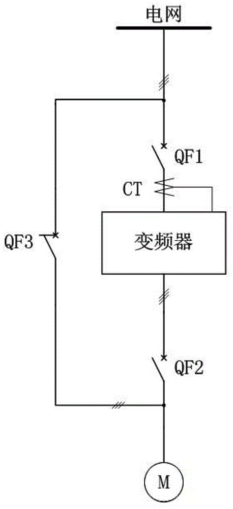
[0020] Such as figure 1 As shown, it is the structural diagram of the existing high-voltage inverter configured with an automatic bypass switch. The input of the high-voltage inverter is connected to the grid through the incoming switch QF1, and the output of the high-voltage inverter is connected to the load motor through the outgoing switch QF2. The frequency bypass switch QF3 is connected to the power grid. When the high-voltage inverter is running normally, the incoming line switch QF1 and the outgoing line switch QF2 are closed, the power frequency bypass switch QF3 is open, and the high-voltage inverter supplies power to the load motor. When the high-voltage inverter fails, the high-voltage inverter immediately blocks the output pulse, and at the same time disconnects the incoming and outgoing switches QF1 and QF2, and then closes the bypass s...


PUM


Abstract

The invention discloses a harmonic wave reactive compensation control method based on a high-voltage inverter bypass. A high-voltage inverter failure bypass reactive compensation circuit comprises an inverter, wherein the inverter is connected with a power grid through an wire inlet switch; a wire outlet end of the inverter is connected to a motor through a three-phase reactor and a wire outlet switch sequentially; a wire inlet end of a bypass switch is connected with a wire inlet end of an inverter wire inlet switch; and a wire outlet end of the bypass switch is connected with a wire outlet end of an inverter wire outlet switch. By the harmonic wave reactive compensation control method based on the high-voltage inverter bypass, a high-voltage inverter device can perform reactive compensation in real time according to motor load after the high-voltage inverter automatically switches the failure into the power frequency to operate, the network side power factor is increased, and the quality of electric energy is improved, so that the utilization ratio of the inverter is increased to the maximum degree and the benefit maximization of users is guaranteed.

Description

technical field [0001] The invention relates to the field of high-voltage frequency converter fault bypass control, and more specifically, relates to a harmonic reactive power compensation control method based on high-voltage frequency converter bypass. Background technique [0002] With the wide application of energy-saving technologies for high-voltage frequency converters in power, metallurgy, petroleum, chemical and other important occasions, higher requirements are put forward for the stability and energy-saving effect of high-voltage frequency converters. The cascaded high-voltage inverter, which consists of several independent power units connected in series, has been favored by more and more industries at home and abroad for its advantages such as small harmonics, convenient and fast unit interchange, mass production, and convenient maintenance. It shows a broad promotion prospect. [0003] Each phase of the unit-cascaded high-voltage inverter is composed of several...

Claims


Application Information

Patent Timeline
Patent Type & Authority Applications(China)
IPC IPC(8): H02J9/04H02P27/04H02J3/18
CPCY02E40/30Y02P20/10
Inventor 杨轶成钱诗宝丁明进霍利杰李冰
Owner 南京国电南自新能源科技有限公司
Why Eureka
Try Eureka