
Check type meter joint

A surface joint and non-return technology, which is applied in the field of surface joints with non-return function, can solve the problems of adding pipe connection parts, easy to cause blockage, and reducing service life, etc. long life effect

Inactive Publication Date: 2015-02-25
董服义
View PDF8 Cites 0 Cited by
  • Summary
  • Abstract
  • Description
  • Claims
  • Application Information

AI Technical Summary

Problems solved by technology

[0003] The use of these check valves increases the number of connecting parts in the pipeline, resulting in high cost, slow construction speed, and increased safety hazards such as leakage.
Furthermore, the existing check valves usually have an inner plug in the valve body. When the reverse flow occurs, the end of the inner plug and the valve body achieve a sealing fit. When the forward flow flows in, the medium flows in from the end of the inner plug. The two sides of the inner plug flow out, and the medium can only flow between the inner plug and the inner wall of the valve. The flow area is small and it is easy to cause blockage; The forward force of the inner plug increases the flow area of ​​this structure, but it is easy to damage and reduces the service life, and the spring is in a compressed state for a long time. When the medium is diverted, it will give the inner plug a pulling force to prevent It moves so that the valve cannot be closed in time

Method used


Image

  • Check type meter joint
  • Check type meter joint
  • Check type meter joint

Examples


Embodiment Construction

[0019] In order to enable those skilled in the art to better understand the solutions of the present invention, the technical solutions in the embodiments of the present invention will be described clearly and completely in conjunction with the accompanying drawings in the embodiments of the present invention.

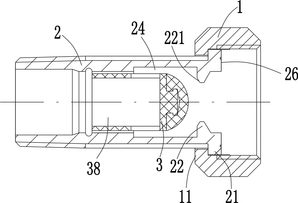
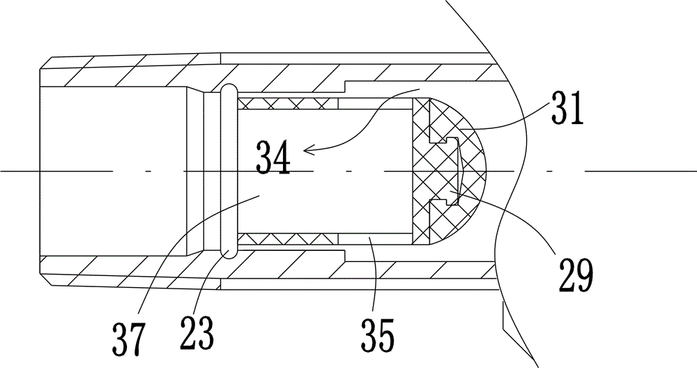
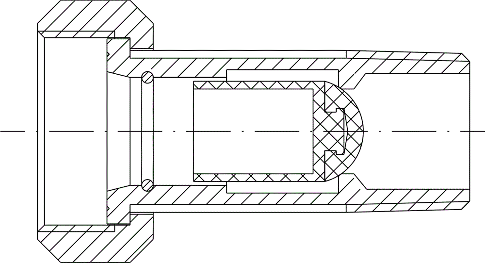
[0020] Such as figure 1 As shown, a non-return type meter connector is installed in front of the watch and includes a connector nut 1 threadedly connected to the meter and a connector tube 2 for connecting with pipe fittings. The inner end of the connector tube 2 and the connector nut 1 contact portion is provided with an annular shoulder 21. The outer end of the joint nut 1 is provided with a retaining edge 11 that is matched with the annular shoulder 21, the inner end of the connecting pipe 2 is provided with a sealing ring seat 26, and the outer end of the outer end is provided with a thread matching the pipe fitting. An inner core 3 that can move back and forth in the ...


PUM


Abstract

The invention discloses a check type meter joint, which comprises a joint screw nut and a connecting pipe, wherein the joint screw nut is connected with a meter tool through screw threads, the connecting pipe is used for being connected with a pipe fitting, the part of the inner end of the connecting pipe in contact with the joint screw nut is provided with an annular convex shoulder, the outer end of the joint screw nut is provided with a baffle edge matched with the annular convex shoulder, the end part of the inner end of the connecting pipe is provided with a sealing ring seat, the end part of the outer end of the connecting pipe is provided with screw threads matched with the pipe element in a surrounding way, an inner card of the connecting pipe is provided with an inner core capable of forwards and backwards moving in the axial direction under the external force effect, one end of the inner core is provided with a plug with the surface covered by flexible materials, a retainer ring realizing the sealed matching with the plug is arranged on the inner wall of the connecting pipe, the inner side part on the inner wall of the connecting pipe, near the retainer ring is provided with a circle of annular groove, a cavity is formed in the inner core, the cavity is provided with an opening in the medium circulation direction, and the side wall of the inner core is communicated with the cavity of the inner core for forming a circulation passage for medium circulation. The meter joint has the advantages that the check structure is simple, the circulation area is large, the lockage cannot easily occur, the service life is long, and the cost is saved.

Description

Technical field [0001] The invention relates to parts of gas, water and liquid metering meters, in particular to a meter joint with a non-return function. Background technique [0002] At present, when tap water or gas is used, a meter is installed to measure the consumption. However, in the traditional installation process, the installation method of the meter is to use a straight ball valve at the inlet end to connect with a meter connector. Then connect with the inlet end of the meter to achieve on-off control of the meter. In tap water pipelines, a check valve is usually installed in front of the ball valve to prevent the medium in the pipeline from flowing back, or the user's water tower water source diversion due to the water supply stoppage, to prevent the meter from inverting or damaging. [0003] The use of these check valves increases the connecting parts in the pipeline, which results in high cost, slow construction speed, and additional safety hazards such as leakage. ...

Claims


Application Information

Patent Timeline
Patent Type & Authority Patents(China)
IPC IPC(8): F16K15/02
Inventor 董服义
Owner 董服义
Learn More