Eureka AIR delivers breakthrough ideas for toughest innovation challenges, trusted by R&D personnel around the world.

Circuit for triggering two-gap plasma jet apparatus

A plasma and spray device technology, applied in the circuit field of the plasma spray device, can solve the problems of reduced work reliability and safety, change of the working performance of the gas switch, limited application of the plasma spray device, etc., so as to increase the safety and Reliability, charging voltage reduction, reliable repeated triggering effect

Active Publication Date: 2013-02-20
西安西交瑞力电气研究院有限公司
View PDF6 Cites 20 Cited by
  • Summary
  • Abstract
  • Description
  • Claims
  • Application Information

AI Technical Summary

Problems solved by technology

Due to the possibility of misoperation of the gas switch, or after multiple triggers, the working performance of the gas switch will change, which will reduce the reliability and safety of the entire system.
[0004] The shortcomings of traditional triggering methods and triggering circuits limit the application of plasma spraying devices to a certain extent

Method used


Image

  • Circuit for triggering two-gap plasma jet apparatus
  • Circuit for triggering two-gap plasma jet apparatus
  • Circuit for triggering two-gap plasma jet apparatus

Examples


Embodiment Construction

[0028] The present invention will be further described in detail below in conjunction with specific embodiments, which are explanations of the present invention rather than limitations.

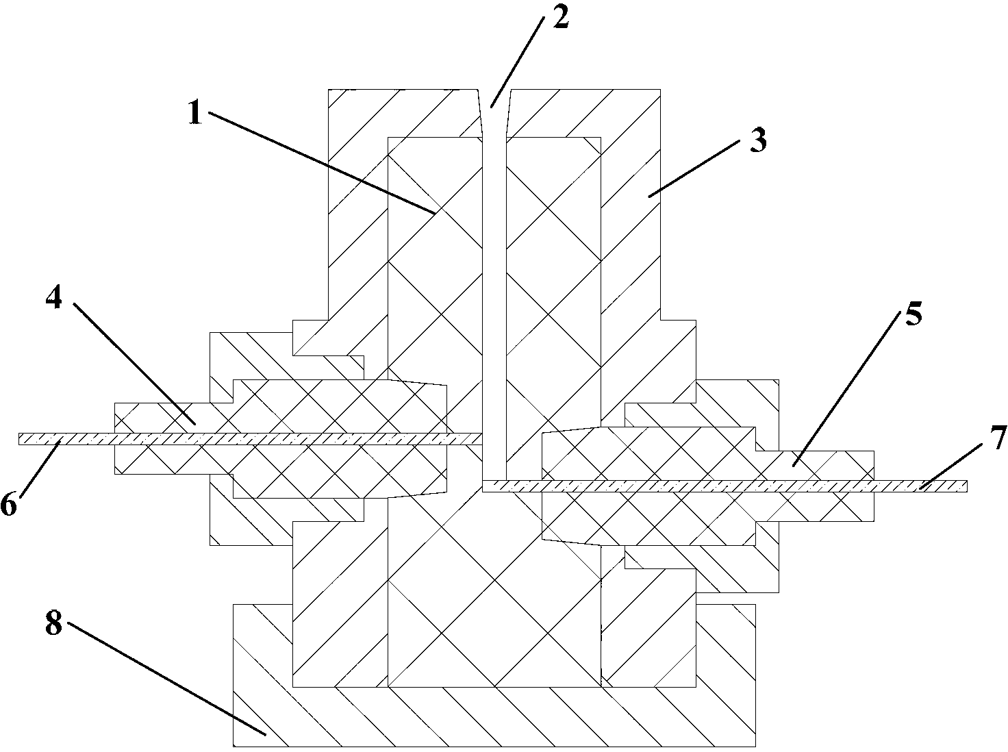
[0029] The present invention provides a circuit for triggering a two-gap plasma injection device having the following figure 1 As shown for illustration, the plasma injection device includes a high-voltage electrode, a medium-voltage electrode and a low-voltage electrode, and the medium-voltage electrode divides the flashover channel into two parts: a short-gap channel and a long-gap channel. In the figure, 3 and 8 are low-voltage electrodes; 4 and 5 are insulating sleeves; 6 is a medium-voltage electrode; 7 is a high-voltage electrode.

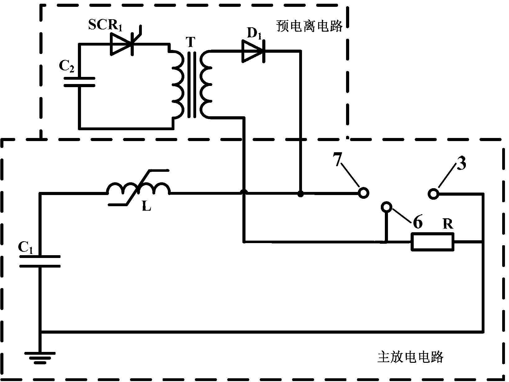
[0030] The circuit for triggering the two-gap plasma injection device includes a pre-ionization circuit and a main discharge circuit, the pre-ionization circuit pre-ionizes the short-gap channel of the two-gap plasma injection device, and then the main disch...


PUM

PropertyMeasurementUnit
Resistanceaaaaaaaaaa

Abstract

The invention discloses a circuit for triggering a two-gap plasma jet apparatus. The circuit for triggering the two-gap plasma jet apparatus comprises a pre-ionization circuit and a main discharge circuit, wherein the pre-ionization circuit pre-ionizes a short gap channel of the two-gap plasma jet apparatus, and then the main discharge circuit discharges to the short gap channel to form plasma jetting and enables a long gap channel of the two-gap plasma jet apparatus to be sparked over and punctured in succession so as to produce a long electric arc running through a sparkover channel of the two-gap plasma jet apparatus. The pre-ionization circuit pre-ionizes the short gap channel in an early stage of discharge, accordingly the charging voltage of a main discharge capacitor is reduced greatly, 1-3kV of voltage can be reduced, and the safety and the reliability of the whole discharge circuit are improved.

Description

technical field [0001] The invention belongs to the technical field of pulse power, and relates to a circuit for triggering a two-gap plasma injection device. Background technique [0002] The plasma injection device based on capillary discharge has been studied as early as the 1940s. Compared with other plasma injection devices, it has a simple structure and can generate plasma under atmospheric conditions, and has a wide range of application prospects. [0003] The traditional plasma injection device adopts the trigger mode of metal detonating wire. When discharging, the metal detonating wire is ablated and dissociated by a large current to generate an electric explosion, thereby forming an arc in the capillary. Using this triggering method, although capillary discharge can be formed at a lower voltage, this triggering method cannot meet the requirements of repeated triggering, that is, the metal detonating wire needs to be replaced every time it is triggered. At the same...

Claims


Application Information

Patent Timeline
IPC IPC(8): H05H1/36
Inventor 杨兰均黄东
Owner 西安西交瑞力电气研究院有限公司
Why Eureka
Eureka Blog
Learn More