Heating control method of TEG reboiler fire tube

A heating control and reboiler technology, applied in chemical instruments and methods, control combustion, lighting and heating equipment, etc., can solve the problems of easy flameout, large inertia, large lag, etc., to solve the problem of reboiler flameout, Optimizing the adjustment and control method of the burner and solving the effect of overshooting the temperature of the TEG solution

Active Publication Date: 2014-12-17
BC P INC CHINA NAT PETROLEUM CORP +1
View PDF9 Cites 0 Cited by
  • Summary
  • Abstract
  • Description
  • Claims
  • Application Information

AI Technical Summary

Problems solved by technology

When the heat load demand increases and the output value of the temperature regulator reaches the upper limit set value, the auxiliary burner will be added to burn, and the newly added auxiliary burner will be controlled by the upper limit value. Due to the large hysteresis, the newly added burner will cause a large overshoot to the temperature of the reboiler, so that the TEG in the reboiler may decompose and deteriorate due to high heat intensity in a short period of time
In addition, since the auxiliary burner is put into combustion according to the opening of the upper limit setting value of the temperature regulator, the mixed gas of fuel gas and air flows out of the burner at a very fast speed when it is put in, and it is easy to blow out the burning burner, especially by When the combustion of 1 burner is increased to 2 burners, the phenomenon of flameout is more likely to occur
[0004] In order to overcome the deficiencies of the current TEG reboiler heating control method, this TEG reboiler fire tube heating control method is mainly to solve the problem of temperature control overshoot, increase the burner and easily cause flameout, make the TEG reboiler heating more stable and reduce TEG Overtemperature decomposition and deterioration loss and energy saving

Method used


Image

  • Heating control method of TEG reboiler fire tube
  • Heating control method of TEG reboiler fire tube
  • Heating control method of TEG reboiler fire tube

Examples


Embodiment Construction

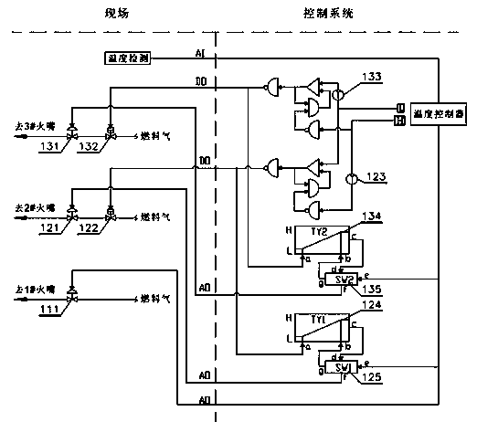
[0013] The TEG reboiler of the present invention adopts multiple burners, and each burner fuel gas pipeline is provided with a fuel gas regulating valve and a fuel gas cut-off valve, which are used to control the burner fuel gas flow and burner switching. In order to prevent the burner from defiring or tempering, each burner is controlled by high and low limit. A specific burner (main burner) among the multiple burners is always put into combustion, and the number of other burners (auxiliary burners) put into combustion is increased or decreased one by one according to the heat load requirement. In order to reduce the impact of adding auxiliary burners on the flame stability of the main burner, the multiple burners of the TEG reboiler are arranged in the lowest layer of the reboiler according to the main burner, and the auxiliary burners are arranged above the main burner. arrangement.

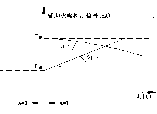
[0014] When the heat load demand of the reboiler changes, the TEG reboiler nozzle switchi...


PUM


Abstract

The invention discloses a heating control method of a TEG reboiler fire tube. According to the heating control method, a linear function generator is added by auxiliary burner ports; when each auxiliary burner port is used for burning, the opening of the fuel gas regulating valve is slowly and steadily increased according to the low limit value of a temperature controller, thereby well solving the problem of temperature overshoot of TEG solution of the reboiler; by reasonably arranging the arraying sequence of the burner ports on the reboiler, the influence of the additionally used auxiliary burner ports on the stability of the flame of a main burner port can be reduced; and by optimizing the burner port regulating and control method, the opening of the fuel gas regulating valve is small when the additionally used auxiliary burner ports are used, the flow speed of fixed fuel gas out of the burner is low, the influence of the additionally used burner ports on the stability of the flame of burnt burner ports is effectively reduced, and the problem of flameout of the reboiler caused by adding of burning of burner ports is fundamentally solved.

Description

technical field [0001] The invention belongs to the technical field of triethylene glycol (TEG) regeneration technology in the petroleum and natural gas industry, and in particular relates to a method for switching burners and controlling temperature of a TEG reboiler. Background technique [0002] In the triethylene glycol dehydration process, the TEG rich liquid after absorbing water needs to be heated and concentrated before it can be recycled. It is the most convenient method to use a direct flame heating fire tube reboiler for heating and concentration. The reboiler is generally operated under normal pressure, and the concentration of TEG will increase with the increase of the temperature of the reboiler. The concentration of TEG rich liquid can generally reach 98%~99% after being regenerated and concentrated by the reboiler. The temperature of the TEG reboiler is generally controlled at about 190~204°C. If the temperature is too high, the TEG will decompose and deterio...

Claims


Application Information

Patent Timeline
Patent Type & Authority Patents(China)
IPC IPC(8): F23N5/00B01B1/00
Inventor 周明军李峰于建林盛炳林
Owner BC P INC CHINA NAT PETROLEUM CORP
Why Eureka
Try Eureka