
Wide-load-range zero-voltage-switching full-bridge transformer for effectively suppressing secondary-side voltage spikes

A technology of zero-voltage switching and full-bridge converters, which is applied in the direction of high-efficiency power electronic conversion, adjustment of electric variables, and output power conversion devices, which can solve the problem of reducing the working reliability and efficiency of converters, and can not eliminate the leakage inductance voltage of transformers. Oscillation, increasing the soft switching range of the lagging arm, etc., to reduce adverse effects, small leakage inductance, and eliminate the loss of secondary side duty cycle

Inactive Publication Date: 2013-02-13
NANJING UNIV OF AERONAUTICS & ASTRONAUTICS
View PDF3 Cites 8 Cited by
  • Summary
  • Abstract
  • Description
  • Claims
  • Application Information

AI Technical Summary

Problems solved by technology

The method of using saturated inductance can significantly increase the soft switching range of the lagging arm, the duty cycle loss is small, and the inductance value of the main power transmission path after the primary side commutation is small can effectively suppress the voltage spike and oscillation of the secondary side, but the saturation The inductor is large in size, which is not conducive to the integration of the converter
Redl et al. used the clamping method of adding clamping diodes on the primary side, which broadened the soft switching range and greatly suppressed the voltage spikes and oscillations of the rectifier diodes. However, the loss of duty cycle caused by the addition of resonant inductors still exists and cannot be eliminated. The voltage oscillation caused by the leakage inductance of the transformer, and the working conditions of the clamping diode are often poor, which reduces the working reliability and efficiency of the converter

Method used


Image

  • Wide-load-range zero-voltage-switching full-bridge transformer for effectively suppressing secondary-side voltage spikes
  • Wide-load-range zero-voltage-switching full-bridge transformer for effectively suppressing secondary-side voltage spikes
  • Wide-load-range zero-voltage-switching full-bridge transformer for effectively suppressing secondary-side voltage spikes

Examples


Embodiment Construction

[0015] Below in conjunction with accompanying drawing, the technical scheme of invention is described in detail:

[0016] attached figure 1 Shown is a schematic diagram of the structure of a traditional zero-voltage switching full-bridge converter.

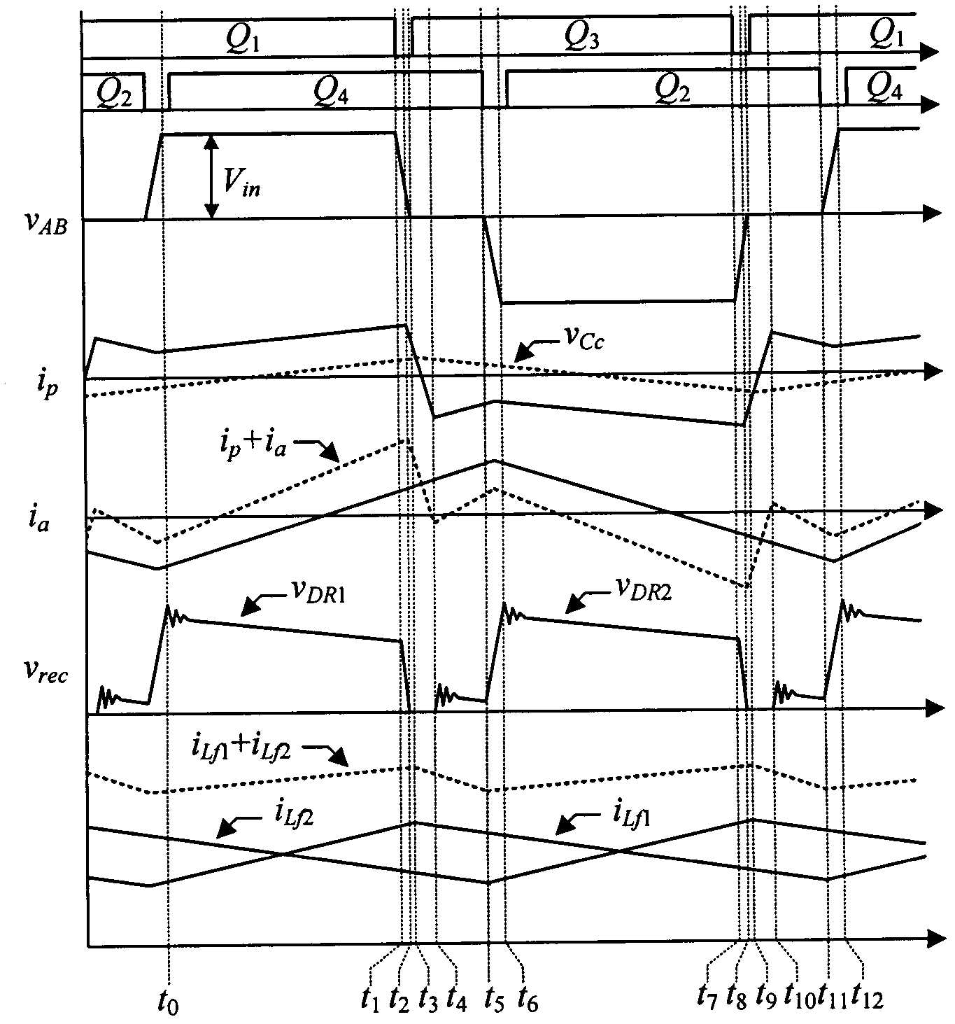
[0017] attached figure 2 What is shown is a schematic diagram of the circuit structure of a zero-voltage switching full-bridge converter with a wide load range that can effectively suppress the voltage spike on the secondary side. by the DC power supply V in , two inverter bridge arms 1 and 2, an isolation transformer 3, an auxiliary inductor 4, an auxiliary capacitor 5, a commutation capacitor 6 and a rectification filter circuit 7. Q 1 ~Q 4 are four power switch tubes, D 1 ~D 4 are the switching tube Q 1 ~Q 4 body diode, C 1 ~C 4 are the switching tube Q 1 ~Q 4 The parasitic capacitance, L a is the auxiliary inductance, C a is the auxiliary capacitor, C c is the commutation capacitor, T r Is an isolation transf...


PUM


Abstract

The invention discloses a wide-load-range zero-voltage-switching full-bridge transformer for effectively suppressing secondary-side voltage spikes. The wide-load-range zero-voltage-switching full-bridge transformer comprises a direct-current power supply, a first inverter bridge arm, a second inverter bridge arm, an auxiliary capacitor, an auxiliary inductor, a current conversion capacitor, an isolation transformer and a rectifying filtering circuit. According to the invention, a phase shift control manner is adopted, by means of additional arrangement of the current conversion capacitor and an LC (Inductive-Capacitive) auxiliary network, the voltage spikes and oscillations of an output rectifying diode are suppressed favorably, the zero-voltage switching of a switch tube in a wide load range can be realized, and meanwhile, the losses of secondary-side duty cycle are eliminated.

Description

technical field [0001] The invention relates to a wide-load-range zero-voltage switching full-bridge converter that can effectively suppress secondary-side voltage spikes. The zero-voltage switching of the switching tube is realized within a wide range of input voltage and load current. Background technique [0002] Direct-to-direct conversion, as an important part in the field of power electronics technology, has received a lot of research in recent years. In medium and high power DC conversion occasions, the full bridge converter has been widely used because the switching tube is easy to realize soft switching and adopts constant frequency control. But the traditional zero-voltage switching full-bridge converter with phase-shift control has serious voltage spikes and oscillations on the secondary side of the transformer. This voltage spike and oscillation is caused by the junction capacitance of the rectifier diode, the leakage inductance of the transformer, and the reso...

Claims


Application Information

Patent Timeline
Patent Type & Authority Applications(China)
IPC IPC(8): H02M3/335H02M1/44
CPCY02B70/1491Y02B70/10
Inventor 陈仲刘沙沙史良辰季锋
Owner NANJING UNIV OF AERONAUTICS & ASTRONAUTICS
Learn More