
Tower-type solar heat collection heliostat field control system based on multi-layer architecture

A tower type solar energy and control system technology, applied in the direction of using feedback control, etc., can solve the problem that the direction of the photosensitive sensor cannot be adjusted in real time, is not suitable for industrial production and market competition, and the performance of the heliostat group controller is high, and achieves high precision. The effect of automatically tracking the sun's running trajectory, the scheduling method and device is reasonable, and improving the working efficiency of the mirror field

Active Publication Date: 2013-02-13
陕西西科博尔科技有限责任公司
View PDF6 Cites 14 Cited by
  • Summary
  • Abstract
  • Description
  • Claims
  • Application Information

AI Technical Summary

Problems solved by technology

[0005] 1. In the prior art, there is no system for controlling the heliostat field combined with large and small spots;
[0006] 2. At present, heliostat controllers usually use expensive bottom-level control units and devices with general functions, most of which are unnecessary functions in the heliostat control process, resulting in waste of resources and not suitable for industrial production and market competition ;
[0007] 3. The heliostat group controllers in the heliostat field have high performance, and there is still room for development and utilization
In the prior art, it is only used as a special subgroup controller, which causes a waste of resources;
[0008] 4. The existing open-closed-loop hybrid control heliostat device based on the photosensitive sensor cannot be adjusted in real time due to the direction pointed by the photosensitive sensor, and some light spots of the mirror field cannot be projected to different positions of the heat collector to realize the monitoring of the surface of the heat collector. Scheduling and control of temperature field

Method used


Image

  • Tower-type solar heat collection heliostat field control system based on multi-layer architecture
  • Tower-type solar heat collection heliostat field control system based on multi-layer architecture
  • Tower-type solar heat collection heliostat field control system based on multi-layer architecture

Examples


Embodiment Construction

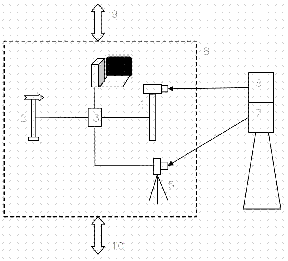
[0040] Field-level scheduling and control devices such as figure 1 As shown, the heliostat field control and scheduling device (8) includes a host (1), a weather monitor (2), a host communication interface (3), an infrared camera (4), and a high-precision camera (5).

[0041] The functions of the host computer (1) are: to receive instructions from the control platform of the tower heat collection system and to feed back relevant information; to send instructions to the control devices of each heliostat mirror group and to receive relevant information fed back; to calculate the geographic location of the mirror site to observe the orbit of the sun Relevant data is sent to each heliostat mirror group; according to the requirements of the time period and the temperature field change of the photothermal conversion system, determine the relevant heliostat mirror group and heliostats that perform tasks such as spot projection and defocusing, and the mirror field processing measures f...


PUM


Abstract

The invention relates to a tower-type solar heat collection heliostat field control system based on a multi-layer architecture. The system is composed of three control levels including a heliostat field scheduling and controlling layer, a heliostat sub-group controlling layer and a sun tracking device layer from top to bottom, wherein the heliostat field scheduling and controlling layer consists of five parts including a heliostat field controlling machine, a weather monitoring device, a field observation device, a communication interface and a light spot checking device; the heliostat sub-group controlling layer is composed of a controller adopting the two-computer backup redundancy technique, and the controller has the function of a bottom-layer heliostat; and the sun tracking device layer consists of the bottom-layer heliostat used for open-loop control and open-loop / closed-loop mixed control.

Description

technical field [0001] The invention relates to the fields of tower solar heat collection systems and industrial automation control, in particular to a tower solar heat collection heliostat field control system based on a multi-layer structure. Background technique [0002] With the market's increasing demand for clean energy, a large number of solar tracking devices that mainly track the sun's orbit have emerged in the field of solar thermal power generation. Among them, the tower solar thermal collection system is higher than other systems such as the trough system and the butterfly system in terms of tracking complexity and precision requirements. Moreover, the tower solar heat collection system has fully demonstrated its superior economic and technological development prospects, which is of great significance for promoting the development of renewable energy. [0003] Tower solar heat collection system technology and equipment are in the early stage of marketization and...

Claims


Application Information

Patent Timeline
IPC IPC(8): G05D3/12
Inventor 王涛明王泽华牛震宇刘晓光汪腾飞马贵鹏周永福姚成生冷贯南陆栋锁兴亚
Owner 陕西西科博尔科技有限责任公司
Learn More