Method for separating ammonia

An absorbent and desorption technology, applied in the field of ammonia separation and production technology for separating ammonia and synthesizing ammonia, can solve the problems of increasing the consumption of raw coal, increasing the amount of circulation, wasting energy, etc. net worth effect

Active Publication Date: 2014-08-20
TIANJIN HENGCHUANG MODERN TOWER TECH
View PDF8 Cites 0 Cited by
  • Summary
  • Abstract
  • Description
  • Claims
  • Application Information

AI Technical Summary

Problems solved by technology

[0003] The traditional condensation ammonia separation method has the following problems: 1. The separation efficiency is relatively low: there are still 2.0-3.2% (v) of ammonia in the separated recycle gas that cannot be separated, and enters the system with the recycle gas, not only It increases the cycle volume of the system, and inhibits the speed of the synthesis reaction, limits the increase in production capacity, and wastes energy; 2. In order to maintain the system pressure and normal production, a certain amount of inert gas needs to be discharged. During this process, hydrogen and nitrogen 3. Ammonia is mainly condensed through the ammonia cooler, which consumes a lot of refrigeration work. Therefore, although the freezing ammonia separation process has been improved many times, its energy consumption is always high.

Method used


Image

  • Method for separating ammonia

Examples


Embodiment Construction

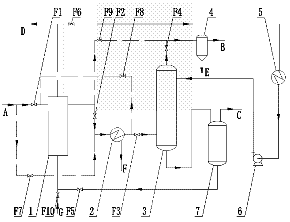
[0012] Further describe the present invention below in conjunction with embodiment and accompanying drawing thereof:

[0013] The method for separating ammonia designed by the present invention (abbreviation method, see figure 1 ,exist figure 1 Among them, the solid arrow line is the process flow of the production stage, and the dotted arrow line is the process flow of the production preparation stage). This method includes the production preparation stage (catalyst heating and reduction stage) and production stage (ammonia separation stage), and the process flow is as follows:

[0014] The production preparation stage of the method of the present invention refers to the stage of temperature raising and reduction of the catalyst that needs to be carried out before normal production. This stage is to use the hydrogen in the cycle gas to reduce the catalyst (the main component is iron oxide) in the synthesis tower to a catalyst with catalytic activity (α-Fe), and it is necessar...


PUM


Abstract

The invention discloses a method for separating ammonia. The method comprises a design of two steps of processes as follows: in a catalyst temperature-rising reduction step, tower gas after heat recovery passes through a gas cooler, a heat exchanger evaporator and a gas-liquid separator in sequence, so that an ammonia water mixture and recycle gas are separated; and in a production step, the tower gas after heat recovery passes through the heat exchange evaporator, the gas cooler, an absorption tower and a gas-liquid separator in sequence, and ammonia and the recycle gas in the tower gas are separated by utilizing a selected solvent; and meanwhile, an absorbent passes through the absorption tower, a flash evaporator, the heat exchange evaporator and an absorbent cooling tower to return to the absorption tower, thus completing the absorption and the desorption of ammonia. The two steps of processes are realized by the switching of two groups of process switching valves, and the two groups of process switching valves are installed in a corresponding process pipeline according to the technological process. Compared with a method for separating ammonia by condensing, the method has the advantages that an ammonia separating ring concept is proposed for the first time, the respective recycling of the recycle gas and the absorbent and the high-efficiency separation of a product can be realized, and the effects of energy conservation and consumption reduction are obvious.

Description

technical field [0001] The invention relates to chemical fertilizer production technology, in particular to a method for separating ammonia. The method adopts an absorption-desorption method to circulate and separate ammonia, and is especially suitable for the ammonia separation production process of synthetic ammonia. Background technique [0002] In the classic synthetic ammonia production process, a certain proportion of hydrogen and nitrogen mixed gas reacts in the ammonia synthesis tower through the action of a catalyst to generate a mixed gas with a certain concentration of ammonia (mainly hydrogen, nitrogen, ammonia and a small amount of inert gas. This is called tower gas), in which the ammonia content is generally 10~20% (v). In order to recycle most of the unreacted hydrogen and nitrogen mixed gas, it is necessary to separate the ammonia in the reacted mixed gas as an ammonia product, and the remaining hydrogen and nitrogen mixed gas (called cycle gas) is returned...

Claims


Application Information

Patent Timeline
Patent Type & Authority Patents(China)
IPC IPC(8): C01C1/12
CPCY02P20/10Y02P20/129
Inventor 杜佩衡孙土金李蓓杜剑婷郑献军姚红果张继军陈学青
Owner TIANJIN HENGCHUANG MODERN TOWER TECH
Why Eureka
Try Eureka