
Erasing mechanism of visual card erasing machine

A visual card and rack technology, which is applied to machines that issue pre-printed tickets, ticketing equipment, instruments, etc., can solve the problems of low erasing efficiency, slow erasing speed, and low erasing efficiency of card surface information, and achieve High erasing efficiency, fast erasing speed, the effect of improving the erasing speed and erasing efficiency of card surface information

Inactive Publication Date: 2014-11-26
NINGBO RONGDA CARD & CERTIFICATE PRINTER MFG
View PDF5 Cites 0 Cited by
  • Summary
  • Abstract
  • Description
  • Claims
  • Application Information

AI Technical Summary

Problems solved by technology

When the video card printer erases the information on the card surface, the bottom surface of the heat-sensitive wiper head in the video card printer is attached to the card surface, and the transmission roller rotates to drive the card to move horizontally. When the card moves horizontally, the card surface and the heat-sensitive There is sliding friction between the bottom surfaces of the wipers, so the friction force between the card surface and the bottom surface of the heat-sensitive wiper head is relatively large, causing great friction damage to the card surface and shortening the service life of the card. The friction on the card surface makes the moving speed of the card slow, and the erasing efficiency of the information on the card surface is low; in addition, after the information on the card surface is erased, the next card can be erased only after the card exits from the card inlet, so the visual card printer adopts The erasing mechanism of the thermal wipe head has slow erasing speed and low erasing efficiency

Method used


Image

  • Erasing mechanism of visual card erasing machine
  • Erasing mechanism of visual card erasing machine
  • Erasing mechanism of visual card erasing machine

Examples


Embodiment Construction

[0016] The present invention will be described in further detail below in conjunction with the accompanying drawings and specific embodiments.

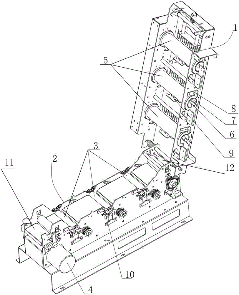
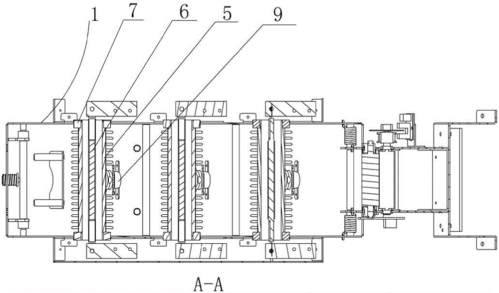
[0017] Such as figure 1 , figure 2 , image 3 , Figure 4 shown;

[0018] The erasing mechanism of the visible card erasing machine of the present invention comprises an upper frame 1 and a lower frame 2, one end of the upper frame 1 and the lower frame 2 is hinged, and the other end is detachably connected, and the lower frame 2 One end of the frame 2 is provided with a bayonet inlet 11, and the lower frame 2 is provided with a motor 4, a control circuit board and a plurality of drive rollers 3, the rotating shaft of the motor 4 is connected with the drive roller 3, and the lower frame The other end of the frame 2 is provided with a bayonet outlet 12; the upper frame 1 is provided with a plurality of heating rollers 5 corresponding to the transmission rollers 3 one by one, and the two ends of each heating roller 5 are connected ...


PUM


Abstract

The invention discloses an erasing mechanism of a visual card erasing machine. The erasing mechanism comprises an upper framework and a lower framework, wherein one ends of the upper and the lower frameworks are hinged, and the other ends of the upper and the lower frameworks are in detachable connection; one end of the lower framework is provided with a card inlet, and the lower framework is equipped with a motor, a control circuit board and a plurality of driving rollers; the rotary shaft of the motor is in driving connection with the driving rollers; the other end of the lower framework is provided with a card outlet; a plurality of heating rollers in one-to-one correspondence with the driving rollers are arranged on the upper framework, and the two ends of each heating roller are rotationally connected with the two side walls of the upper framework; when the upper framework and the lower framework are close, the outer side wall of each heating roller tightly presses and is jointed with the outer side of one corresponding driving roller, and each heating roller is externally equipped with a heating body; the two ends of the heating body are fixedly connected with the outer side wall of the upper framework; and the heating body is connected with the control circuit board via a wire. The erasing machine of the visual card erasing machine is small in damage to the card surface, fast in erasing speed and high in erasing efficiency.

Description

technical field [0001] The invention relates to the technical field of erasing information on the surface of a video card, in particular to an erasing mechanism of a video card erasing machine. Background technique [0002] At present, people use visible card printers to store information in the chip inside the card or in the magnetic strip on the card surface, and can directly print the information on the surface of the card, and can also erase the information on the card surface when it is used next time. Printing, so as to realize the high-tech product of card surface information rewriting. The structure of this video card printer generally includes a lower frame and an upper frame, one end of the lower frame and the upper frame is hinged, and the other end is detachably connected; the upper frame is equipped with a print head and a wiper. In addition to the heat-sensitive wiping head for visual card surface information, the lower frame is provided with a bayonet inlet, ...

Claims


Application Information

Patent Timeline
Patent Type & Authority Patents(China)
IPC IPC(8): G07B3/00
Inventor 宛东亮吴常君杜晶
Owner NINGBO RONGDA CARD & CERTIFICATE PRINTER MFG
Learn More