Sealing method for lateral side of sintering machine

A sintering machine and end sealing technology, which is applied to the sealing of the engine, mechanical equipment, engine components, etc., can solve the problems of not being able to prevent air leakage, and achieve the effects of preventing air leakage, avoiding resistance loss, and reducing air volume

Active Publication Date: 2015-05-20
SHANDONG PROVINCE METALLURGICAL ENG CO LTD
View PDF8 Cites 0 Cited by
  • Summary
  • Abstract
  • Description
  • Claims
  • Application Information

AI Technical Summary

Problems solved by technology

The sealing device of the existing sintering machine is divided into two parts: the end sealing device and the side sealing device; the disadvantage of the side sealing device is that it cannot prevent the air leakage at the end face of the adjacent sintering trolley

Method used


Image

  • Sealing method for lateral side of sintering machine
  • Sealing method for lateral side of sintering machine
  • Sealing method for lateral side of sintering machine

Examples


Embodiment 1

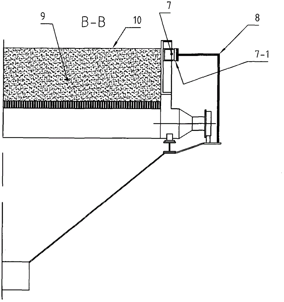
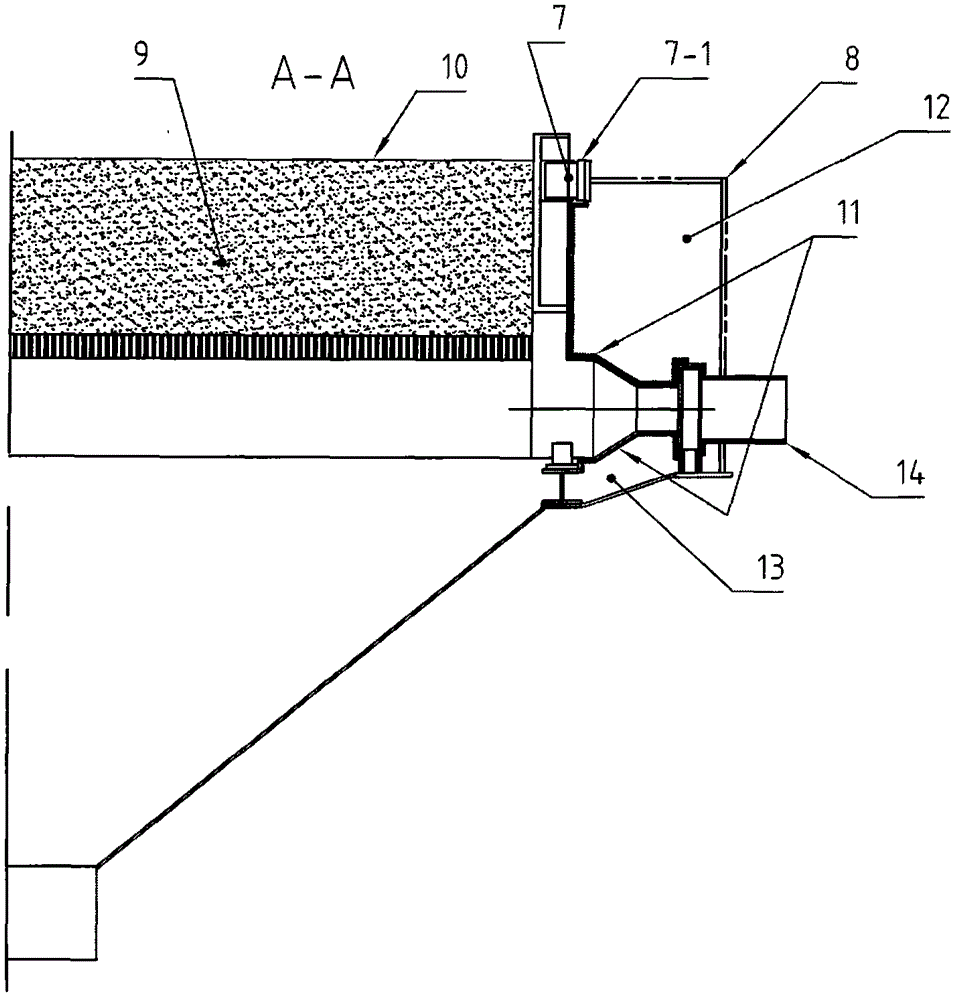
[0019] Example 1, such as figure 1 , figure 2 and image 3 shown.

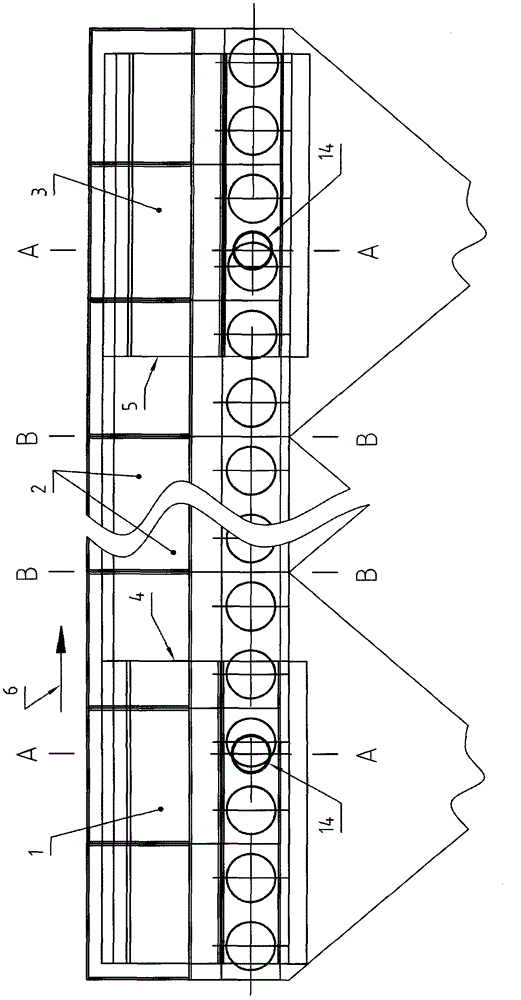
[0020] figure 1 It is a side view of Embodiment 1 of the present invention to express the overall overview of this embodiment.

[0021] from figure 1 It can be seen from the figure that this embodiment is divided into 3 large sections: 1 is the front end sealing section. 2 is the middle segment. 3 is the end sealing section at the rear. 4 and 5 are the interface between the front end sealing section 1 and the rear end sealing section 3 and the middle section 2 respectively. And the arrow 6 represents the running direction of the sintering machine trolley. And 14 is the air introduction port that is provided with at the described trough type end sealing mechanism place. Induction of air through the air inlet 14 can prevent the air leakage of the sintering machine from entering the main exhaust fan, avoid the subsequent resistance loss caused by the air leakage air volume, and reduce the power of the...


PUM


Abstract

The invention provides a sealing method for a lateral side of a sintering machine and belongs to the technical field of sealing of the sintering machine. The sealing method includes use of a sliding-plate and fish-plate type sealing mechanism. The sealing method is characterized in that a sealing cover is arranged between the outer side of a fence plate of a sintering pallet and an air box of the sintering machine, the sliding-plate and fish-plate type sealing mechanism is arranged at an adjacent position of the fence plate of the sintering pallet to the sealing cover, a sliding plate of the sliding-plate and fish-plate type sealing mechanism is mounted on the sealing cover, the sliding-plate and fish-plate type sealing mechanism is positioned between the middle and the upper surface of a material layer of the sintering pallet, an end sealing section is arranged on the sealing cover, and the sealing mechanism on the end sealing section is of a trench type structure. By the aid of the sealing method, air leakage on an end face of the neighboring sintering pallet can be effectively prevented, power of a main suction fan of the sintering machine is lowered, and energy conservation is achieved or performance of the sintering machine is improved.

Description

technical field [0001] The invention relates to a side sealing method of a sintering machine, belonging to the technical field of sintering machine sealing. Background technique [0002] Sintering machine is a kind of equipment widely used in metallurgical enterprises. The air leakage rate of the sintering machine is generally as high as 50%, or even higher. The sealing device of the existing sintering machine is divided into two parts: the end sealing device and the side sealing device; wherein, the disadvantage of the side sealing device is that it cannot prevent air leakage at the end faces of the adjacent sintering trolleys. Contents of the invention [0003] The purpose of the present invention is to provide a side sealing method of a sintering machine to overcome the problems in the prior art. [0004] The main technical problem to be solved in the present invention is: [0005] Air leakage occurring at the end faces of adjacent sintering pallets is prevented. ...

Claims


Application Information

Patent Timeline
Patent Type & Authority Patents(China)
IPC IPC(8): F27B21/08F16J15/06
Inventor 黄东生贠汝平钱纲
Owner SHANDONG PROVINCE METALLURGICAL ENG CO LTD
Why Eureka
Try Eureka