Fuel supply device

A fuel supply device and fuel technology, which are applied to liquid fuel feeders, liquid fuel engines, components of pumping devices for elastic fluids, etc., can solve problems such as increased pressure loss, increased pressure loss, and steam generation. Achieve stable pump discharge, suppress suction, and control fuel pressure stability

Inactive Publication Date: 2015-01-28
MITSUBISHI ELECTRIC CORP
View PDF6 Cites 0 Cited by
  • Summary
  • Abstract
  • Description
  • Claims
  • Application Information

AI Technical Summary

Problems solved by technology

[0008] Alternatively, the fuel is disturbed by the reciprocating action of the piston or a return spring that exerts a return force on the piston
Both of these situations increase the pressure loss, which tends to generate vapors (bubbles) in the fuel
[0009] In addition, since the swirl flow formed substantially parallel to the cylinder end face is in the direction perpendicular to the suction port, the fuel drawn into the suction port is sucked into the suction port after turning sharply at right angles from the flow direction of the swirl flow, resulting in pressure increased losses

Method used


Image

  • Fuel supply device
  • Fuel supply device
  • Fuel supply device

Examples


Embodiment approach 1

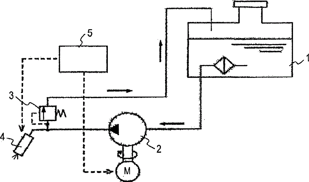
[0062] figure 1 It is a configuration diagram of a fuel system using the fuel supply device of the present invention.

[0063] The fuel supply device 2 is driven based on a drive signal from the control unit 5, and the fuel supply device 2 sucks fuel from the fuel tank 1 through a filter and discharges it.

[0064] The discharged fuel is regulated to a predetermined pressure by the pressure regulator 3 and supplied to the fuel injection device 4 via a high-pressure fuel pipe.

[0065] The fuel injection device 4 controls the injection timing and injection amount based on the engine speed and load, etc., according to a drive signal from the control unit 5, and injects fuel into the intake pipe.

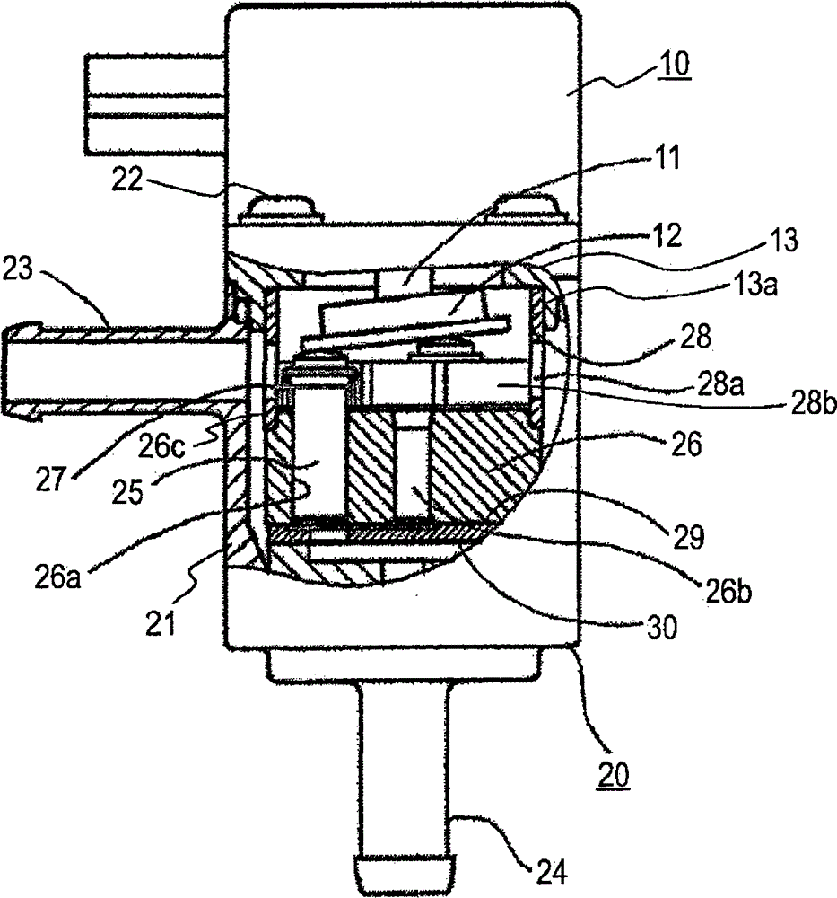
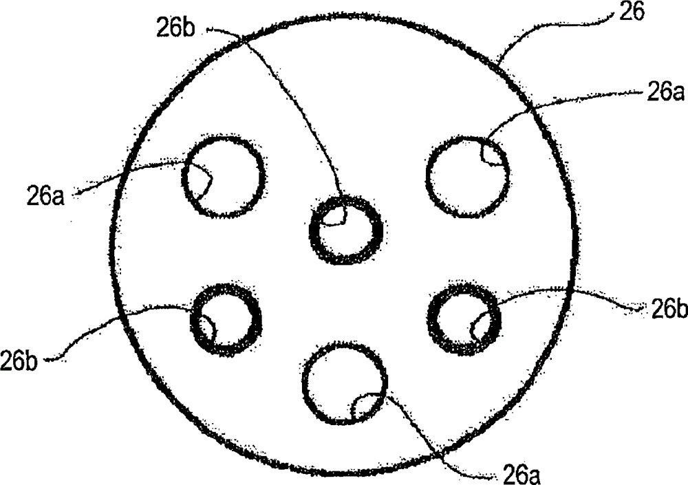
[0066] figure 2 It is a block diagram showing the fuel supply device 2 according to Embodiment 1 of the present invention. image 3 is a plan view of the cylinder of Embodiment 1, Figure 4 It is a side view showing the liner and cylinder of Embodiment 1, Figure 5 yes Figure 4...

Embodiment approach 2

[0091] Figure 8 It is a plan view showing the liner and the cylinder according to Embodiment 2 of the present invention, Figure 9 yes Figure 8 C-C section view. Such as Figure 8 , Figure 9 As shown, the bushing 28 of the second embodiment has a partition wall 28d formed to surround the inlet of the suction port 26b in a cylindrical shape.

[0092] According to the second embodiment, similar to the first embodiment, the fuel near the suction port 26b is less affected by the swirling flow, and the vapor generated by the reciprocating operation of the piston 25 can be suppressed from being sucked into the suction port 26b.

Embodiment approach 3

[0094] Figure 10 It is a plan view showing the liner and the cylinder according to Embodiment 3 of the present invention, Figure 11 yes Figure 10 D-D cutaway view, Figure 12 It is a sectional view showing the positional relationship between the bush and the suction joint in the third embodiment.

[0095] The bushing 28 according to Embodiment 3 is provided with a partition wall 28e surrounding the outer periphery of the piston 25, and a recessed fuel passage 28f connected to the plurality of suction ports 26b.

[0096] Additionally, if Figure 12 As shown, one end of the fuel passage 28f opens at a position substantially opposite to the suction joint 23 formed in the casing 21 .

[0097] According to the third embodiment, as in the first embodiment, the fuel located near the suction port 26b is less likely to be affected by the swirling flow, and the piston 25 is fitted and inserted into the hole 28g formed in the partition wall 28e of the bushing 28, so that It is su...


PUM


Abstract

A fuel supply device is disclosed. Through a simple structure, the fuel supply device is capable of realizing reduction of fuel suction pressure loss, restraint of steam suction, prevention of the phenomena that steam stays inside a pump, stable pump output, stability control over fuel pressure, and the like. In the fuel supply device, a pump part (20) is driven through an electric motor part (10), fuel pumped in the pump part (20) is pressurized and discharged. The pump part (20) comprises a housing (21) equipped with a suction connection head (23) and a discharge connection head (24), an oil cylinder (26) which is accommodated inside the housing and equipped with multiple pistons (25), a shaft (11) arranged at the electric motor part (10), an inclined plate (12) which enables reciprocating motion of the multiple pistons, multiple suction ports (26b) which serve as fuel passageways for guiding the fuel into a plenum chamber and a bush (28) which is roughly cylindrical-shaped, wherein the multiple suction ports (26b) run through the cylinder in an axial direction in such a way that the suction ports correspond to all pistons, two end parts of the bush are inserted and kept in the oil cylinder and the electric motor part, fuel pumped in through the suction connection head is guided to multiple suction ports, and the pistons (25) and the suction ports (26b) are disposed in different spaces (28c) which are separated from each other.

Description

technical field [0001] The present invention relates to a fuel supply device for supplying fuel to, for example, a fuel injection device of an internal combustion engine. Background technique [0002] The piston type fuel pump disclosed in Patent Documents 1 and 2 includes: a swash plate driven by an electric motor; and a cylinder having a plurality of pistons reciprocating with the rotation of the swash plate, and a cylinder for introducing fuel into the cylinder is provided on the inlet side of the cylinder. Suction port of the pressurized chamber. [0003] prior art literature [0004] patent documents [0005] Patent Document 1: Japanese Patent Laid-Open No. 2009-108683 [0006] Patent Document 2: Japanese Patent Laid-Open No. 2011-26962 [0007] In this kind of fuel supply device, due to the rotation of the motor rotor and the rotation of the swash plate, a swirling flow is likely to be generated in the fuel in the pump, and the fuel sucked into the suction port of ...

Claims


Application Information

Patent Timeline
Patent Type & Authority Patents(China)
IPC IPC(8): F04B1/22F04B53/16F04B53/00F02M37/08
Inventor 瓜生拓也大西善彦篠原龙
Owner MITSUBISHI ELECTRIC CORP
Why Eureka
Try Eureka