
Pedestrian leg buffer beam of automobile bumper

A technology for automobile bumpers and anti-collision beams, which is applied in the direction of bumpers, pedestrian/passenger safety arrangements, and vehicle components, and can solve the problems of plastic deformation of the calf anti-collision beams, increased cost of parts, and failure to recover, so as to reduce acceleration and Effect of ligament shear displacement, low production and maintenance costs, and reduced injury value

Active Publication Date: 2013-02-06
YANFENG PLASTIC OMNIUM AUTOMOTIVE EXTERIOR SYST
View PDF7 Cites 14 Cited by
  • Summary
  • Abstract
  • Description
  • Claims
  • Application Information

AI Technical Summary

Problems solved by technology

[0004] (1) No pedestrian calf anti-collision beam structure, the disadvantage is that when the vehicle collides with the pedestrian, the calf will have a large bending angle, which will increase the pedestrian calf injury value
[0005] (2) The calf anti-collision beam is a slender and thin-walled sheet metal structure. The disadvantage is that when the vehicle collides with the pedestrian's calf, the calf anti-collision beam of the sheet metal structure will produce large plastic deformation and cannot be recovered, so it needs to be replaced This part, resulting in an increase in part cost
However, the existing plastic calf anti-collision beam does not fully consider the impact of its structure on the stiffness of the calf anti-collision beam and the impact on the pedestrian's calf injury value, and only has a first-level energy-absorbing area. When the protection test is required, it is relatively difficult to adjust the stiffness, which may lead to difficulties in mold modification, or even re-opening the mold, which greatly increases the production cost and product development cycle

Method used


Image

  • Pedestrian leg buffer beam of automobile bumper
  • Pedestrian leg buffer beam of automobile bumper
  • Pedestrian leg buffer beam of automobile bumper

Examples


Embodiment Construction

[0020] The specific implementation manners of the present invention will be described in detail below in conjunction with the accompanying drawings.

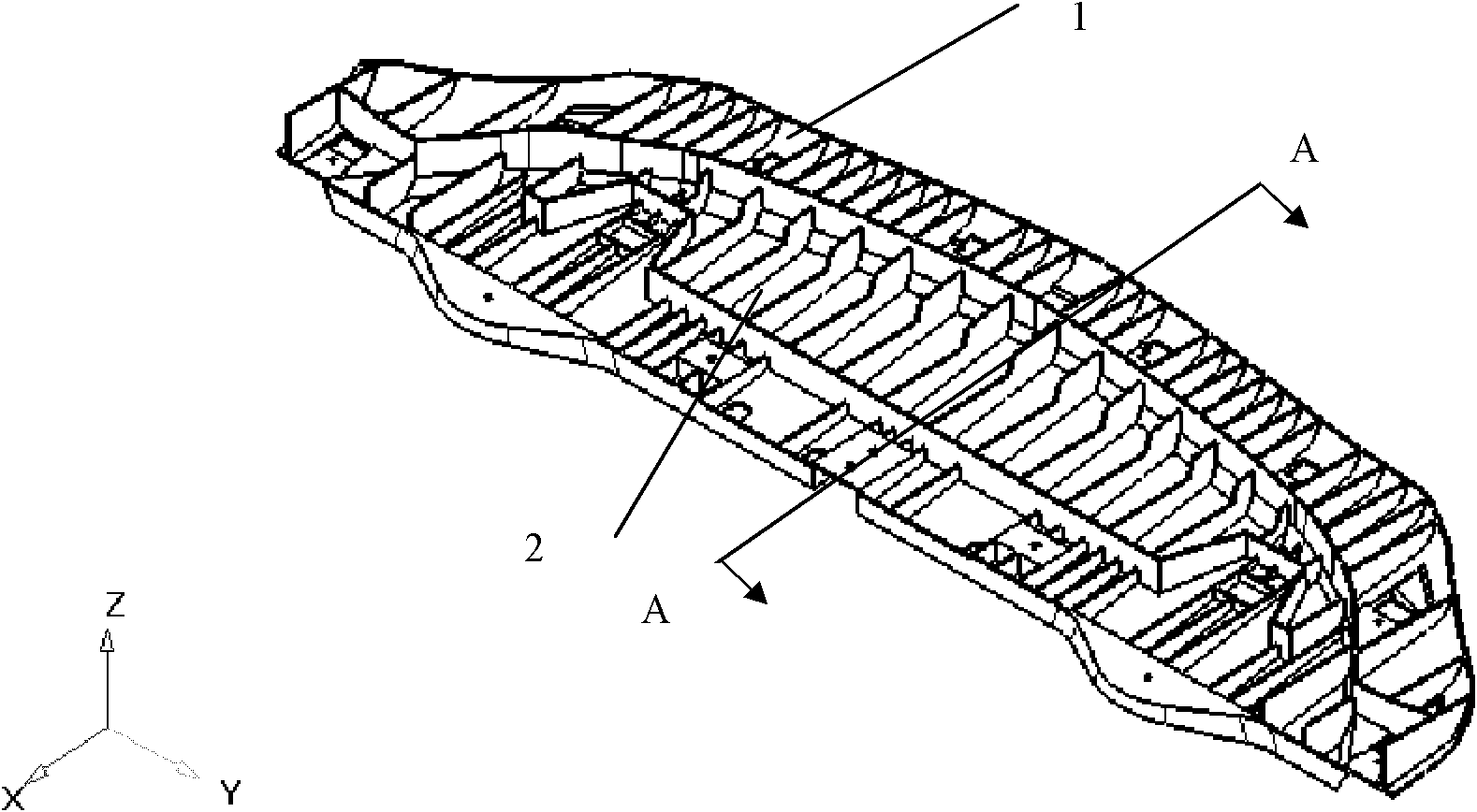
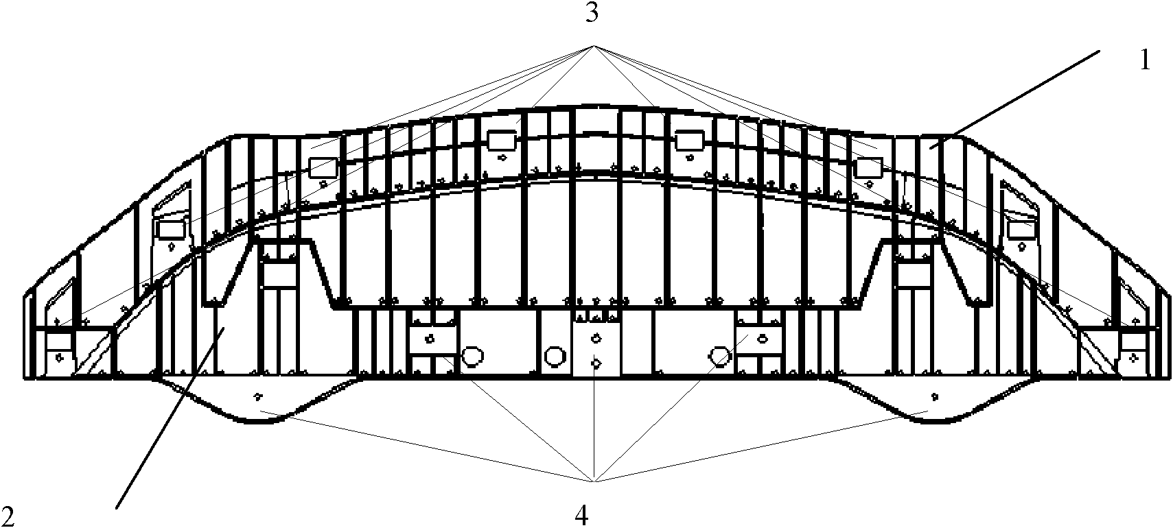
[0021] figure 1 , figure 2 Shown the pedestrian shank anti-collision beam of the automobile bumper of the present invention, this shank anti-collision beam is made of plastics, one end is connected with the bumper (not shown) by 8 C-type nut clamps 3, and the other end is connected by 5 C-type nut clips 3 Bolts 4 are connected to the front frame (not shown) of the vehicle body. Along the direction from the bumper to the body, i.e. figure 1 In the X direction, the shank anti-collision beam includes a primary energy-absorbing area 1 and a secondary energy-absorbing area 2 adjacent to each other, wherein the position of the primary energy-absorbing area 1 in the vertical direction is higher than that of the secondary energy-absorbing area 2 ,Such as image 3 As shown, and the secondary energy-absorbing region 2 includes a bott...


PUM


Abstract

The invention provides a pedestrian leg buffer beam of an automobile bumper. One end of the buffer beam is connected with the bumper, and the other end is connected with a front end skeleton of a automobile body. Along the direction from the bumper to the automobile body, the pedestrian leg buffer beam comprises a primary energy absorption area and a secondary energy absorption area which are adjacently connected with each other, wherein the primary energy absorption area is higher than the secondary energy absorption area in the vertical direction. The rigidity of the pedestrian leg buffer beam of an automobile bumper is easily controlled, so that the injury on pedestrian legs is reduced during impact, and the production cost and the maintenance cost are lower.

Description

technical field [0001] The invention belongs to the technical field of automobile manufacturing, and in particular relates to a pedestrian calf anti-collision beam of an automobile bumper. Background technique [0002] With the development of automobile technology and the improvement of people's safety awareness, the protection of automobiles is no longer limited to the protection of passengers in the car, but has been extended to pedestrians who collide with the car. When a car collides with pedestrians, usually the body directly Contact with the pedestrian's calf, thus directly causing injury to the pedestrian's calf, is difficult to meet the requirements of the national standard GB / T 24550-2009. [0003] The bumper system of prior art is divided into following situations: [0004] (1) No pedestrian calf anti-collision beam structure, the disadvantage is that when a vehicle collides with a pedestrian, the calf will have a large bending angle, which will increase the injur...

Claims


Application Information

Patent Timeline
Patent Type & Authority Applications(China)
IPC IPC(8): B60R19/18B60R21/34
Inventor 徐德奎黄海龙
Owner YANFENG PLASTIC OMNIUM AUTOMOTIVE EXTERIOR SYST
Learn More