Eureka AIR delivers breakthrough ideas for toughest innovation challenges, trusted by R&D personnel around the world.

Automatic injection pump

An automatic injection and syringe technology, which is applied in the field of medical devices, can solve the problems of bending deformation of the lead screw 92, twisting and deformation of the thread, poor tooth meshing, etc., and achieves the effect of ensuring the injection accuracy and prolonging the service life.

Active Publication Date: 2013-02-06
MEDCAPTAIN MEDICAL TECH
View PDF5 Cites 13 Cited by
  • Summary
  • Abstract
  • Description
  • Claims
  • Application Information

AI Technical Summary

Problems solved by technology

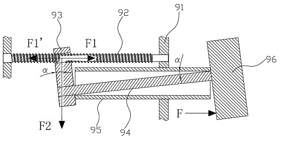
[0005] The above is the general composition and working conditions of the syringe pump, among which there are deficiencies: such as figure 1 As shown, from the perspective of force analysis, in the working process of the syringe pump, the push block 96 pushes the piston of the syringe to move forward through the piston rod, and the piston rod of the syringe gives the push block 96 a reaction force F, so that the solid shaft 94 and the hollow tube 95 forms a "seesaw" effect. When the upper edge of the solid shaft 94 touches the upper edge of the hollow tube 95, the solid shaft 94 reaches the maximum inclination angle α, and the inclination angle of the cotter nut 93 relative to the screw rod 92 is also α. Although the angle α is relatively small (generally 3~5°), long-term inclination of the cotter nut 93 will cause the thread of the cotter nut 93 to be twisted and deformed, increasing the radial pressure F2 and F2 of the cotter nut 93 on the screw rod 92 The increase of F2 will easily cause the bending deformation of the screw rod 92, and the increase of F2 will also make the tooth shape of the split nut 93 and the screw rod 92 poorly meshed, resulting in increased wear of the screw teeth between the screw rod 92 and the split nut 93, which eventually leads to injection The injection accuracy of the pump is not high, and the life of the syringe pump is greatly reduced
In addition, since the split nut 93 is in an inclined state, the axial pressure F1 exerted by the split nut 93 on the screw rod 92 decreases, so the axial thrust F1' applied by the screw rod 92 to the split nut 93 also decreases, thus causing the split nut 93 to The thrust transmitted to the push block 96 also decreases, which affects the normal injection of the syringe and reduces the injection accuracy of the syringe pump.

Method used


Image

  • Automatic injection pump
  • Automatic injection pump
  • Automatic injection pump

Examples


Embodiment Construction

[0023] The following will clearly and completely describe the technical solutions in the embodiments of the present invention with reference to the drawings in the embodiments of the present invention.

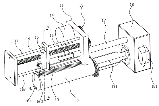
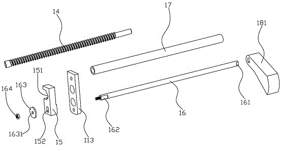
[0024] Such as Figure 2~Figure 4 As shown, an automatic injection pump provided by the embodiment of the present invention includes a frame 11, a driving device 12, a reduction device 13, a screw rod 14, a split nut 15, a solid shaft 16, a hollow tube 17, a push block 18 and a syringe 19 , the two ends of the screw rod 14 are rotatably connected with the frame 11 through bearings (not shown), the split nut 15 has a gap 151, the gap 151 of the split nut 15 is threadedly connected with the screw rod 14, and the split nut 15 passes through the gap 151 The cotter nut 15 can be engaged or separated from the screw rod 14. The solid shaft 16 is arranged in the hollow tube 17. One end of the hollow tube 17 is in contact with the cotter nut 15, and the other end of the hollow tube 17 ...


PUM


Abstract

The invention belongs to the field of medical apparatus and instruments and provides an automatic injection pump. In the working process of the automatic injection pump, when a solid shaft inclines, a second stopper inclines with the solid shaft; after inclining, the second stopper still keeps a certain distance with the first stopper; the second end of the solid shaft can vertically move downwards in an inner hole and a limiting groove of the first stopper of a baffle, so that the first stopper and a nut keep vertical positions unchanged, namely the first stopper and the nut does not incline, so that radial pressure of the nut to a screw rod is the minimum, but axial pressure of the nut to the screw rod is not decreased, namely the loss of the axial thrust which is applied by the screw rod to the nut is minimum, threads between the screw rod and the nut are not abraded intensively, injection precision of the injection pump is ensured, and the service life of the injection pump is prolonged.

Description

technical field [0001] The invention belongs to the field of medical equipment, in particular to an automatic injection pump. Background technique [0002] Such as figure 1 As shown, the transmission device of the existing automatic injection pump is generally a screw nut transmission device, which is mainly composed of a frame 91, a motor (not shown), a speed reduction device (not shown), a screw rod 92, a split nut 93, a solid shaft 94, a hollow tube 95, a push block 96 and a syringe (not shown) are composed of these parts, wherein the screw mandrel 92 is arranged on the frame 91 and can rotate at the original position on the frame 91, and the cotter nut 93 and The screw rod 92 is threaded, and the split nut 93 has a gap, so that the split nut 93 can be engaged with or separated from the screw rod 92. The solid shaft 94 is arranged in the hollow tube 95, and one end of the solid shaft 94 is fixedly connected with the split nut 93. The solid shaft 94 The other end is fixe...

Claims


Application Information

Patent Timeline
Patent Type & Authority Applications(China)
IPC IPC(8): A61M5/145
Inventor 李冬岑胡攀
Owner MEDCAPTAIN MEDICAL TECH
Why Eureka
Eureka Blog
Learn More