Damper

A damper and damping component technology, applied in shock absorbers, shock absorbers, liquid shock absorbers, etc., can solve problems such as high cost and manual execution

Inactive Publication Date: 2014-09-24
ILLINOIS TOOL WORKS INC
View PDF5 Cites 0 Cited by
  • Summary
  • Abstract
  • Description
  • Claims
  • Application Information

AI Technical Summary

Problems solved by technology

The biasing of said spring during damper installation has to be performed manually and entails considerable expense

Method used


Image

  • Damper
  • Damper
  • Damper

Examples


Embodiment Construction

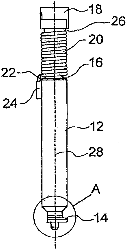
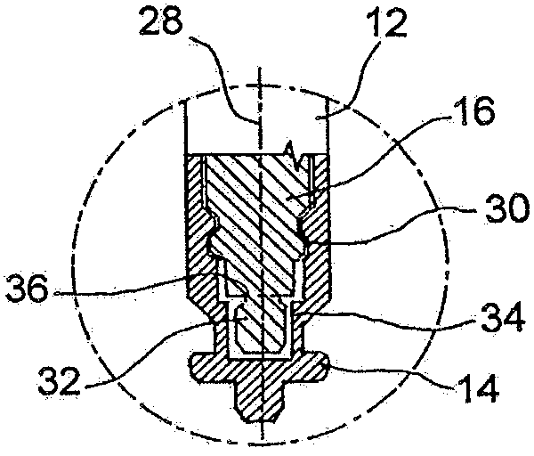
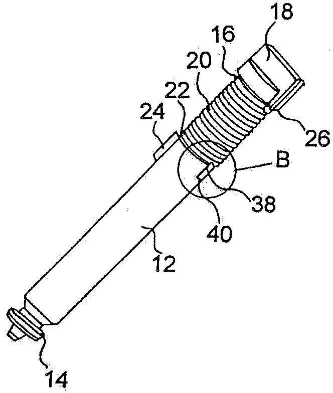
[0027] Unless otherwise indicated, the same reference numerals in each figure indicate the same objects. figure 1 with 2 The damper according to the present invention is shown for damping the movement of a component, such as a cover provided inside an automobile. The damper has a damper housing 12, which is substantially cylindrical in this example. The damper housing 12 defines a cavity that is also substantially cylindrical in which the damper fluid (such as silicone fluid) is located. The damper housing 12 has a protrusion 14 at its front end, thereby enabling the damper to be installed in a component in a reliable anti-rotation manner. The damper also has a damper element 16, which in this case is a substantially cylindrical rotating piston 16 partially located in the damper housing 12. The rotating piston 16 has a matching head 18 at its end remote from the damper housing 12, and the head 18 is also used for mounting on the component. The rotary piston 16 is rotatably in...


PUM


Abstract

Damper for dampening the movement of a component, in particular a component in the interior of an automobile, comprising a damper housing and a damper element being located at least partially within the damper housing and being moveable with regard to the damper housing, and a spring element being in operational connection with the damper element and biasing the damper element in a first moving direction, wherein mechanical locking means are provided which inhibit a movement of the damper element with regard to the damper housing at least in the first moving direction when the spring element is biased, and in that the mechanical locking means are releasable.

Description

Technical field [0001] The present invention relates to a damper for damping the movement of a component, especially a component inside an automobile. The damper includes: a damper housing; a damper element at least partially located in the damper housing The body is capable of moving relative to the damper housing; a spring element is operatively connected with the damper element and biases the damper element in a first direction of movement. Background technique [0002] This type of damper is used, for example, for the damping drive of automotive interior parts, especially covers, fins or grips. The spring element provides a bias, thereby causing the component to move in the first direction in a damped manner, for example after the lock is released. The damper housing often contains a damper fluid, such as a silicone fluid, in which the damper element moves. Due to the interaction with the damper fluid, the movement is damped. Rotating springs are often used as spring eleme...

Claims


Application Information

Patent Timeline
Patent Type & Authority Patents(China)
IPC IPC(8): F16F9/12F16F9/32
CPCF16F9/12F16F2230/0041F16F9/3271
Inventor 于尔根·本诺·希尔珀特
Owner ILLINOIS TOOL WORKS INC
Why Eureka
Try Eureka