High-voltage reactive power automatic compensation device
A technology of automatic power compensation and high voltage, which is applied in the field of high-voltage reactive power automatic compensation device, can solve problems such as insufficient stability, complicated connection of device lines, and low power quality of the power grid, so as to achieve small voltage fluctuations, improve safety and stability, The effect of low power consumption
- Summary
- Abstract
- Description
- Claims
- Application Information
AI Technical Summary
Problems solved by technology
Method used
Image
Examples
Embodiment 1
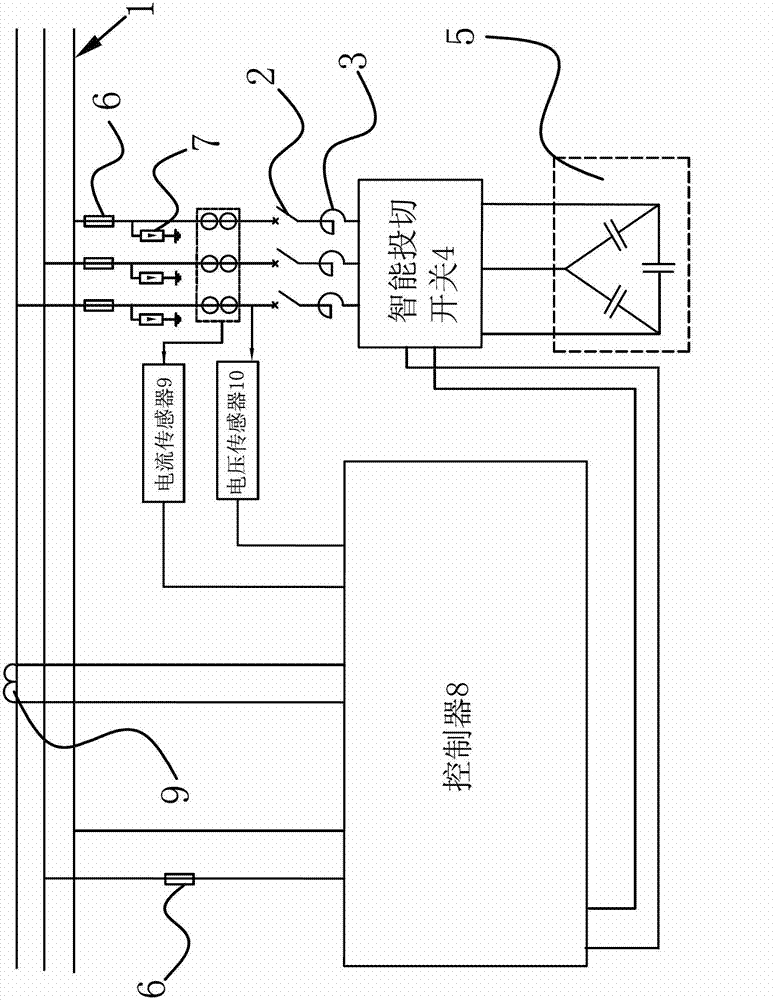
[0027] Such as figure 1 As shown, the high-voltage reactive automatic compensation device includes a vacuum circuit breaker 2 and a switching capacitor group 5 for changing the power factor. The incoming side of the vacuum circuit breaker 2 is connected to the three-phase bus 1, and the outgoing side of the vacuum circuit breaker 2 is sequential A reactor 3 and an intelligent switching switch 4 are connected in series, and the intelligent switching switch 4 is connected to the switching capacitor group 5. The device also includes a controller 8, a current sensor 9 for detecting the current of each phase of the three-phase bus 1 and a The voltage sensor 10 for detecting the voltage of each phase of the three-phase bus 1, the current sensor 9 and the voltage sensor 10 are all connected to the input terminal of the controller 8, and the output terminal of the controller 8 is connected to the intelligent switching switch 4; the vacuum circuit breaker 2 and the three-phase A fuse 6...
Embodiment 2
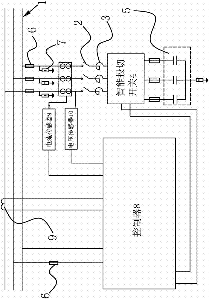
[0035] Such as figure 2 As shown, the content of the second embodiment is basically the same as that of the first embodiment, the difference is that in the high-voltage reactive power automatic compensation device, the switching capacitor group 5 includes three switching capacitors connected in a star shape, and the three switching capacitors A lightning protection circuit 7 is connected to the connection point of the switching capacitor, and a fuse 6 is connected in series between the other ends of the three switching capacitors and the intelligent switching switch 4 . The switching capacitor group 5 is connected with one end of three switching capacitors to form a star structure, and the connection point of the star structure is connected to the lightning protection circuit 7, which can effectively prevent the occurrence of lightning tripping accidents on the transmission line. Reliable protection is provided; the other ends of the three switching capacitors are respectivel...
Embodiment 3
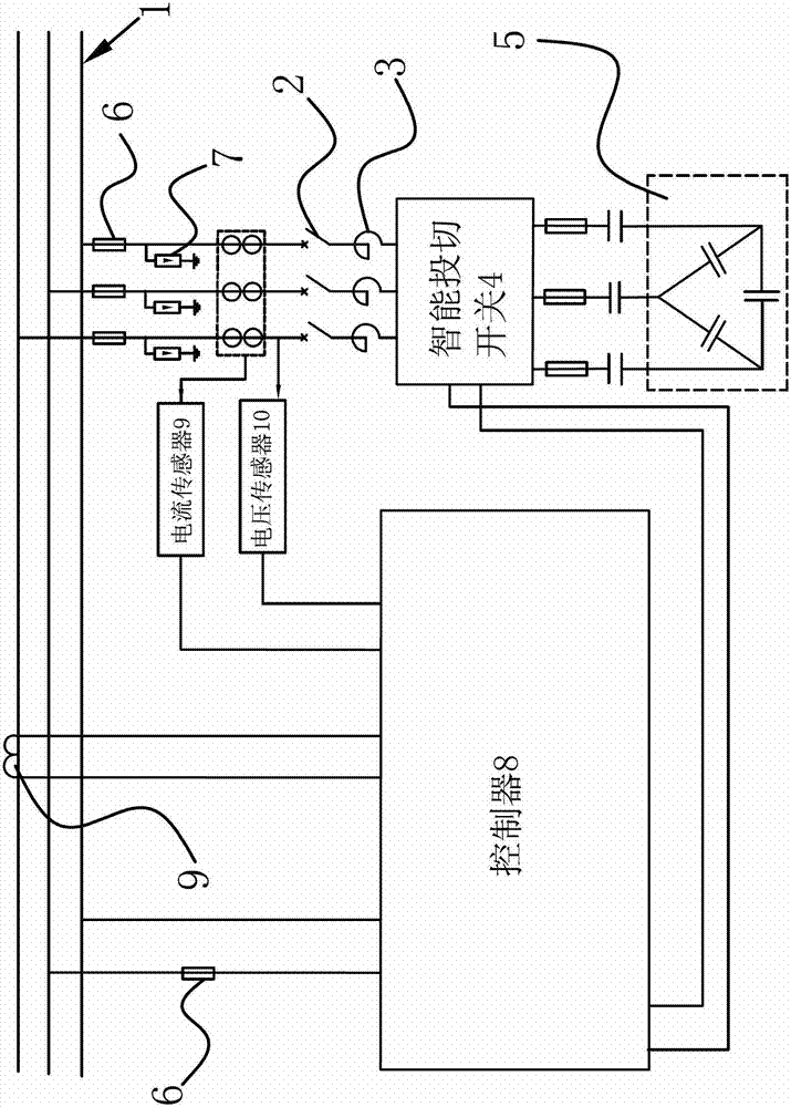
[0037] Such as image 3 As shown, the content of the third embodiment is basically the same as that of the first embodiment, the difference is that in the high-voltage reactive power automatic compensation device, the switching capacitor group 5 includes three switching capacitors connected in a triangle, and the switching capacitors A capacitor and a fuse 6 are respectively connected in series between the connection point and the intelligent switching switch 4 . The connection points of two switching capacitors are respectively connected to the intelligent switching switch 4 through capacitors and fuses 6. Once the line has a short-circuit fault, the fuse 6 will jump off immediately, which can effectively prevent damage to the switching capacitor group 5 and the line; And in this embodiment, the reactor 3 and the switching capacitor connected in the line form an LC tuning circuit for a specific harmonic, so that the filter branch has a very low impedance to a certain harmonic...
PUM
 Abstract
Description
Claims
Application Information
 - R&D
- Intellectual Property
- Life Sciences
- Materials
- Tech Scout
- Unparalleled Data Quality
- Higher Quality Content
- 60% Fewer Hallucinations
Browse by: Latest US Patents, China's latest patents, Technical Efficacy Thesaurus, Application Domain, Technology Topic, Popular Technical Reports.
© 2025 PatSnap. All rights reserved.Legal|Privacy policy|Modern Slavery Act Transparency Statement|Sitemap|About US| Contact US: help@patsnap.com


