Overall Composite Bulging Technology of Automobile Drive Axle
A drive axle, bulging technology, applied in the field of machining, can solve the problems of difficult to control bulging force, heavy weight, easy to produce cracks, etc.
- Summary
- Abstract
- Description
- Claims
- Application Information
AI Technical Summary
Problems solved by technology
Method used
Image
Examples
no. 1 example
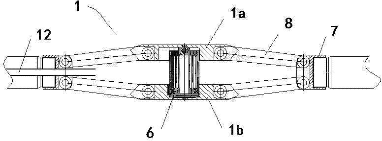
[0070] Such as figure 1 As shown, it is a schematic diagram of the structure of the first embodiment of the overall composite bulging device of the automobile drive axle suitable for the overall composite bulging process of the automobile drive axle of the present invention after the bulging deformation of the workpiece is completed, which is shown as a mechanical push rod type bulging method; figure 2 It is a structural schematic diagram of the integral composite bulging device of the automobile drive axle in this embodiment before the workpiece is bulging and deformed.
[0071] The integral composite bulging device of the automobile drive axle in this embodiment includes a bulging inner mold 1 , a bulging outer mold 2 and a bulging force generating device for applying bulging force to the bulging inner mold 1 . The bulging inner mold 1 includes an upper module 1a and a lower module 1b respectively matched with the upper and lower inner walls of the axle housing pipa bag 5a,...
no. 2 example
[0087] Figure 5 It is a structural schematic diagram of the second embodiment of the integral compound bulging device of the automobile drive axle suitable for the integral compound bulging process of the automobile drive axle of the present invention after the bulging deformation of the workpiece is completed, which is shown as a spiral thrust bulging method; Image 6 It is a structural schematic diagram of the integral composite bulging device of the automobile drive axle in this embodiment before the workpiece is bulging and deformed.
[0088] The two thrust devices in this embodiment are the thrust hydraulic cylinder 3 and the thrust hydraulic cylinder 4 which are respectively located at both ends of the bulging inner mold 1 and are used to provide thrust. Apply hydraulic pressure to the end. The pressure generating device of this embodiment is at least one multi-stage hydraulic cylinder 6 arranged between the upper module 1a and the lower module 1b, and the multi-stage ...
no. 1 Embodiment
[0118] The wall thickness of the axle housing workpiece 5 of the present embodiment is 1.5 mm, and its specific process parameters of bulging deformation are as follows:
[0119] 1. Thermal expansion method:
[0120] 1) The axle housing workpiece 5 is heated to 600°C during bulging deformation
[0121] In the yield stage of the deformation of the axle housing workpiece 5, the maximum bulging force required by the axle housing workpiece is 2000-2200KN and fluctuates with the yield strain law of the axle housing workpiece shell. The thrust of the thrust hydraulic cylinder 3 and the thrust hydraulic cylinder 4 is 0KN, the maximum pressure of the multi-stage hydraulic cylinder 6 acting on the upper module 1a and the lower module 1b is 2000-2200KN and fluctuates with the yield strain law of the axle housing workpiece;
[0122] In the bulging stage of the deformation of the axle housing workpiece 5, the bulging force required by the axle housing workpiece 5 gradually increases to 9...
PUM
| Property | Measurement | Unit |
|---|---|---|
| thickness | aaaaa | aaaaa |
| mechanical properties | aaaaa | aaaaa |
| mechanical properties | aaaaa | aaaaa |
Abstract
Description
Claims
Application Information
 - R&D
- Intellectual Property
- Life Sciences
- Materials
- Tech Scout
- Unparalleled Data Quality
- Higher Quality Content
- 60% Fewer Hallucinations
Browse by: Latest US Patents, China's latest patents, Technical Efficacy Thesaurus, Application Domain, Technology Topic, Popular Technical Reports.
© 2025 PatSnap. All rights reserved.Legal|Privacy policy|Modern Slavery Act Transparency Statement|Sitemap|About US| Contact US: help@patsnap.com


