
Posterolateral tibial plateau condyle anatomical plate

A tibial plateau and posterolateral technology, applied in the field of tibial plateau posterolateral condyle anatomical plate, can solve the problems of inability to reset, lose, and inability to expose the fracture end of the posterolateral condyle, etc., and achieve the effect of firm fixation and convenient installation

Inactive Publication Date: 2013-01-23
储旭东
View PDF13 Cites 3 Cited by
  • Summary
  • Abstract
  • Description
  • Claims
  • Application Information

AI Technical Summary

Problems solved by technology

[0002] Fracture of the posterolateral condyle of the tibial plateau is a special intra-articular fracture. Although the traditional anterolateral approach is safe, the fracture of the posterolateral condyle cannot be exposed due to the obstruction of the fibular head. Even if it is barely exposed, it cannot be reduced well. Relying on traditional hollow nails, L-shaped steel plates or golf plates cannot effectively fix the collapsed bone block from front to back, and fracture displacement and loss of articular surface height are prone to occur in the later stage
The anatomical relationship between the posterior median approach and the posterolateral approach is complicated. It is necessary to expose the blood vessels and nerves, cut off the gastrocnemius and popliteus muscles, and ligate the inferior lateral arteries of the knee, which is easy to damage the nerves and blood vessels, and has a certain impact on the stability of the knee joint. Clear, the installation of internal fixation is inconvenient, and it is difficult to remove the internal fixation for the second time

Method used

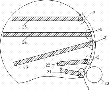

Image

  • Posterolateral tibial plateau condyle anatomical plate
  • Posterolateral tibial plateau condyle anatomical plate

Examples


Embodiment Construction

[0011] The preferred embodiments of the present invention are given below in conjunction with the accompanying drawings to describe the technical solution of the present invention in detail.

[0012] Such as figure 1 As shown, the tibial plateau posterolateral condyle anatomical plate of the present invention includes a head region A, a neck region B and a body region C, and the head region A has a flank region D, which specifically includes a first locking screw hole 1, a second locking screw hole Screw hole 2, third locking screw hole 3, fourth locking screw hole 4, fifth locking screw hole 5, sixth locking screw hole 6, overlapping hole 7, first meniscal suture hole 8, second meniscus Suture hole 9, third meniscus suture hole 10, plate body 11, first locking screw hole 1, second locking screw hole 2, third locking screw hole 3, fourth locking screw hole 4, fifth locking screw hole 5 , the sixth locking screw hole 6, the overlapping hole 7, the first meniscus suture hole 8,...


PUM

PropertyMeasurementUnit
Diameteraaaaaaaaaa
Diameteraaaaaaaaaa

Abstract

The invention discloses a posterolateral tibial plateau condyle anatomical plate, comprising a first locking screw hole, a plate body and other elements, wherein the first locking screw hole, a second locking screw hole, a third locking screw hole, a fourth locking screw hole, a fifth locking screw hole, sixth locking screw holes, overlapped holes, a first meniscal suture hole, a second meniscal suture hole and a third meniscal suture hole are all located on the L-shaped plate body, the first meniscal suture hole, the second meniscal suture hole and the third meniscal suture hole are located above the first locking screw hole, the second locking screw hole, the third locking screw hole, the fourth locking screw hole and the fifth locking screw hole, the four sixth locking screw holes are located below the first locking screw hole, the second locking screw hole, the third locking screw hole, the fourth locking screw hole and the fifth locking screw hole, and the overlapped holes are located below the sixth locking screw holes. The posterolateral tibial plateau condyle anatomical plate disclosed by the invention is convenient to mount, immobile and firm, and safe and effective.

Description

technical field [0001] The invention relates to a steel plate for a medical device, in particular to an anatomical steel plate for the posterolateral condyle of the tibial plateau. Background technique [0002] Fracture of the posterolateral condyle of the tibial plateau is a special intra-articular fracture. Although the traditional anterolateral approach is safe, the fracture end of the posterolateral condyle cannot be exposed due to the obstruction of the fibular head. Even if it is barely exposed, it cannot be reduced well. Relying on traditional hollow nails, L-shaped plates or golf plates cannot effectively fix the collapsed bone from front to back, and fracture displacement and loss of articular surface height are prone to occur in the later stage. The anatomical relationship between the posterior median approach and the posterolateral approach is complex. It is necessary to expose the blood vessels and nerves, cut off the gastrocnemius and popliteus muscles, and liga...

Claims


Application Information

Patent Timeline
IPC IPC(8): A61B17/80
Inventor 储旭东
Owner 储旭东
Learn More