
Photovoltaic module mounting structure and mounting method thereof

A photovoltaic module and installation structure technology, applied in the support structure of photovoltaic modules, photovoltaic modules, photovoltaic power generation and other directions, can solve the problems of poor mechanical strength of the system, complicated processing of accessories, complicated and tedious installation, etc. The effect of high mechanical strength

Active Publication Date: 2013-01-16
TRINA SOLAR CO LTD
View PDF3 Cites 8 Cited by
  • Summary
  • Abstract
  • Description
  • Claims
  • Application Information

AI Technical Summary

Problems solved by technology

Among these installation systems, although some systems are simple in structure and easy to install, they have poor mechanical strength and complex parts processing, and some systems have simple parts processing and high mechanical structure, but their installation is complicated and cumbersome, requiring a lot of labor costs

Method used


Image

  • Photovoltaic module mounting structure and mounting method thereof
  • Photovoltaic module mounting structure and mounting method thereof
  • Photovoltaic module mounting structure and mounting method thereof

Examples


Embodiment Construction

[0030] Embodiments of the present invention will now be described in detail with reference to the accompanying drawings. Reference will now be made in detail to the preferred embodiments of the invention, examples of which are illustrated in the accompanying drawings. Wherever possible, the same numbers will be used throughout the drawings to refer to the same or like parts. In addition, although the terms used in the present invention are selected from well-known and commonly used terms, some terms mentioned in the description of the present invention may be selected by the applicant according to his or her judgment, and the detailed meanings thereof are set forth herein described in the relevant section of the description. Furthermore, it is required that the present invention be understood not only by the actual terms used, but also by the meaning implied by each term.

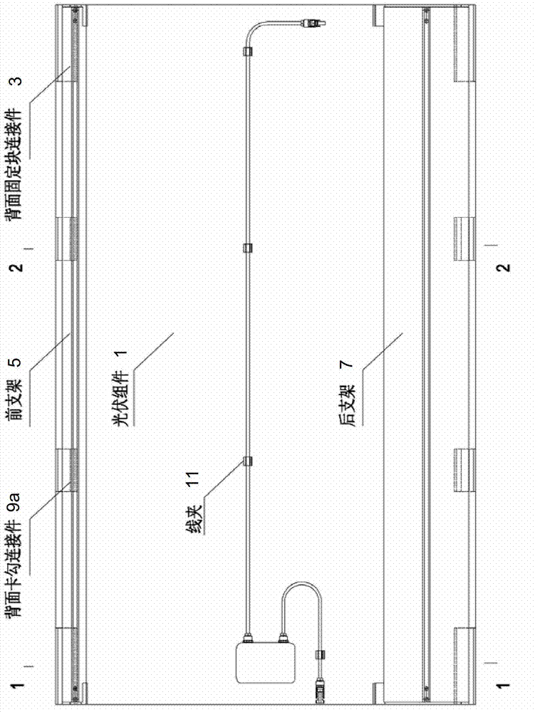
[0031] figure 1 A rear view of a frameless photovoltaic module system according to an aspect of the p...


PUM


Abstract

The invention provides a photovoltaic module mounting structure and a mounting method thereof. The photovoltaic module mounting structure comprises a plurality of photovoltaic modules, and each photovoltaic module is connected with a first back fixing block connector, a first back clamping hook connector, a second first back fixing block connector and a second back clamping hook connector, wherein the first back fixing block connectors and the first back clamping hook connectors are connected to first sides of the photovoltaic modules and further connected to a front support combination; and the second first back fixing block connectors and the second back clamping hook connectors are connected to second sides of the photovoltaic modules and further connected to a rear support combination. The front support combination is capable of freely rotating around the first back fixing block connectors and the first back clamping hook connectors, and the rear support combination is capable of freely rotating around the second first back fixing block connectors and the second back clamping hook connectors.

Description

technical field [0001] The invention relates to the field of solar photovoltaic component installation and component manufacturing, in particular to a solar photovoltaic system component and its installation structure applied to building flat roofs. Background technique [0002] At present, the installation technology of crystalline silicon solar photovoltaic modules is relatively mature. Generally speaking, a large number of solar photovoltaic modules are installed on the sunny side of the house or the ground by using installation structures such as installation frames. [0003] In the existing technology, many photovoltaic manufacturers and system installers have their own structural installation systems for photovoltaic module installation systems suitable for flat roofs, such as KYOCERA solar installation structures, Panelclaw solar installation solutions, and Sunlink installations. modules, the Schletter mounting system, and more. Among these installation systems, alth...

Claims


Application Information

Patent Timeline
Patent Type & Authority Applications(China)
IPC IPC(8): H01L31/042H01L31/18H02S20/24H02S30/00
CPCY02E10/50Y02B10/10Y02P70/50
Inventor 蒋阿华
Owner TRINA SOLAR CO LTD
Learn More