
Capacitive voltage transformer failure monitoring instrument

A voltage transformer and fault monitoring technology, applied in the direction of measuring current/voltage, instruments, measuring devices, etc., can solve the problems of high operating risk and low reliability of the system, and achieve the goal of reducing operating risks, stable and reliable parameters, and improving system reliability. sexual effect

Inactive Publication Date: 2013-01-16
ELECTRIC POWER RES INST OF STATE GRID ZHEJIANG ELECTRIC POWER COMAPNY +1
View PDF9 Cites 20 Cited by
  • Summary
  • Abstract
  • Description
  • Claims
  • Application Information

AI Technical Summary

Problems solved by technology

[0005] In view of this, the present invention provides a capacitive voltage transformer fault monitoring instrument to overcome the system operation caused by the need to change the equipment structure and the monitored parameters being affected by the environment in the prior art. High risk, low reliability issues

Method used


Image

  • Capacitive voltage transformer failure monitoring instrument
  • Capacitive voltage transformer failure monitoring instrument
  • Capacitive voltage transformer failure monitoring instrument

Examples


Embodiment 1

[0042] Such as figure 1 As shown, the capacitive voltage transformer connected to the three-phase bus in this embodiment adopts a three-phase symmetrical installation method.

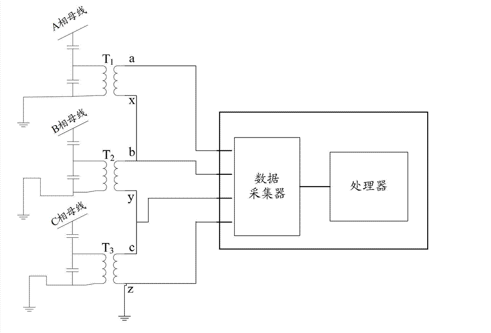
[0043] figure 2 It is a schematic structural diagram of a capacitive voltage transformer fault monitoring instrument disclosed in an embodiment of the present invention,

[0044] image 3 It is a schematic diagram of the wiring of the capacitive voltage transformer fault monitoring instrument disclosed in the embodiment of the present invention,

[0045] see figure 2 and image 3 As shown, the capacitive voltage transformer fault monitoring instrument 20 may include:

[0046] A data collector 201 for collecting the secondary voltage of each phase of the three-phase capacitive voltage transformer.

[0047] see image 3 As shown, in this embodiment, the three-phase capacitive voltage transformers are connected by the open triangle method, the two pins on the secondary side of the A-phase capaciti...

Embodiment 2

[0074] Figure 10 It is a schematic diagram of the second structure of the capacitive voltage transformer fault monitoring instrument disclosed in the embodiment of the present invention, see Figure 10 As shown, the capacitive voltage transformer fault monitoring instrument 100 may include:

[0075] A data collector 201 for collecting the secondary voltage of each phase of the three-phase capacitive voltage transformer.

[0076] Connect with the data collector, process the secondary voltage of each phase to obtain any one or more parameters of the three-phase open triangle voltage, voltage unbalance and voltage transformer amplitude, and judge the three-phase open Whether any one or more of the triangular voltage, voltage unbalance degree and voltage transformer amplitude exceeds the preset standard range, and if the judgment result is yes, the processor 202 sends out a corresponding limit alarm.

[0077] Connected with the processor 202, a memory 203 storing a table of cor...


PUM


Abstract

The invention discloses a capacitive voltage transformer failure monitoring instrument, which can acquire the three-phase secondary voltage of a three-phase capacitive voltage transformer, can acquire parameter information to be known by processing and calculating the three-phase secondary voltage, and can judge whether the capacitive voltage transformer is abnormal and fails according to the parameter information. During application, the capacitive voltage transformer failure monitoring instrument provided by the embodiment of the invention is directly connected to power equipment, the conventional power equipment structure is not required to be changed, reference parameters of failure judgment are directly calculated by the output voltage of the capacitive voltage transformer, the parameters are stable and reliable, the operating risk of a power system is reduced, and the reliability of the system is improved.

Description

technical field [0001] The invention relates to the field of capacitive voltage transformers, in particular to a fault monitoring instrument for capacitive voltage transformers. Background technique [0002] Capacitive voltage transformer is a transformer with capacitive voltage divider and iron core, mainly composed of capacitive voltage divider, primary coil, secondary coil, iron core and insulation. figure 1 It is a schematic diagram of the installation and connection of the capacitor voltage transformer in the grid, such as figure 1 As shown, the capacitive voltage transformer is usually arranged in a three-phase symmetrical installation in the substation. The number of winding turns on the primary coil and the secondary coil are different, and the high voltage can be divided into the number of turns of the primary winding and the number of turns of the secondary winding. ratio converted to low voltage. Therefore, the capacitive voltage transformer is an electrical dev...

Claims


Application Information

Patent Timeline
Patent Type & Authority Applications(China)
IPC IPC(8): G01R19/165
Inventor 何文林王文浩孙翔刘浩军林群梅冰笑
Owner ELECTRIC POWER RES INST OF STATE GRID ZHEJIANG ELECTRIC POWER COMAPNY
Learn More