
High-low temperature dynamic cold-hot circulation thermodynamic test system

A technology of cold and heat cycle and test system, which is applied in the direction of applying stable tension/pressure to test the strength of materials, scientific instruments, measuring devices, etc. question

Inactive Publication Date: 2014-09-24
TSINGHUA UNIV
View PDF4 Cites 1 Cited by
  • Summary
  • Abstract
  • Description
  • Claims
  • Application Information

AI Technical Summary

Problems solved by technology

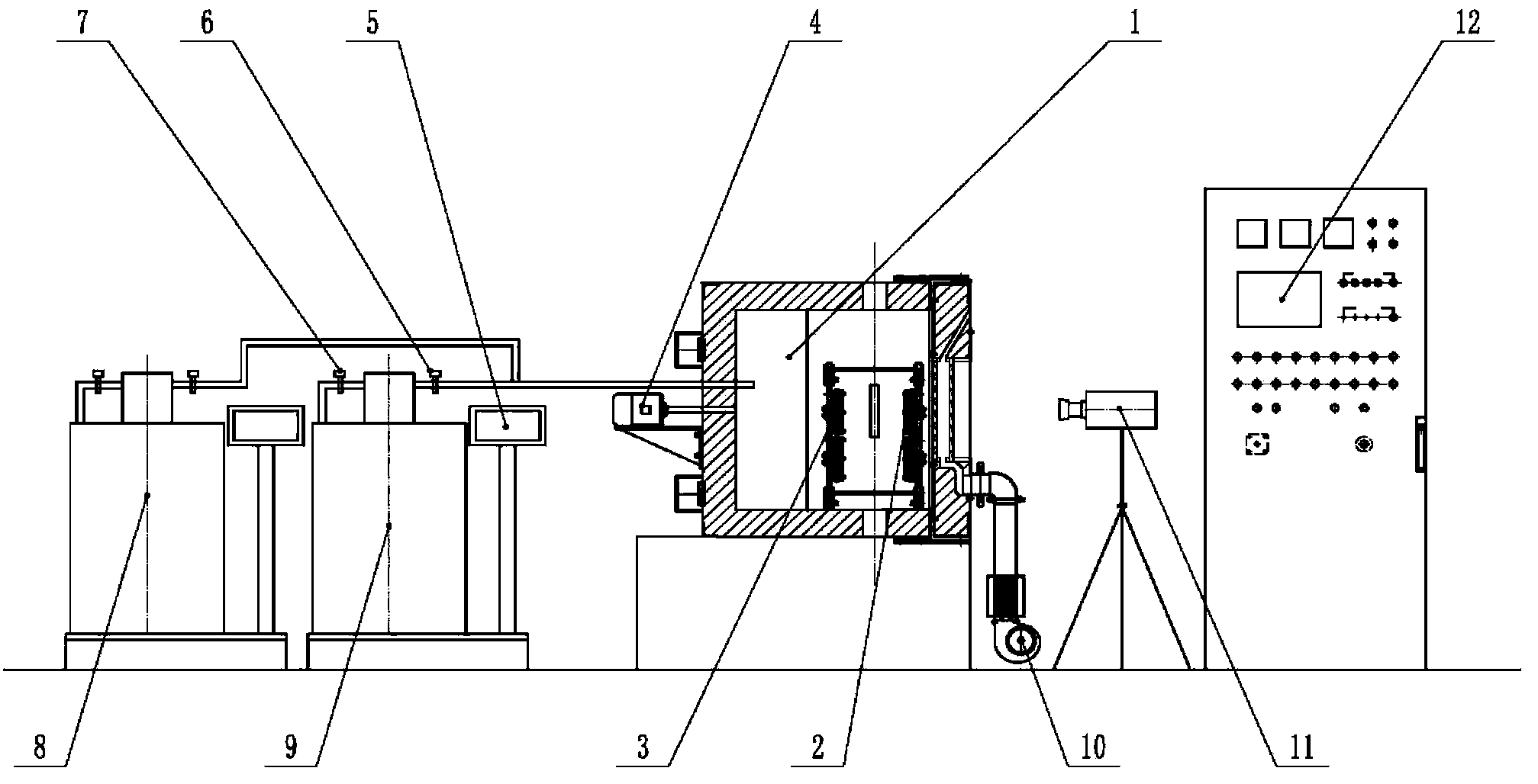
[0003] In order to make up for the lack of thermal transient and thermal cycle defects in the existing thermodynamic test system for thermal steady-state environment, low-temperature refrigeration is limited by the capacity of the liquid nitrogen tank and cannot provide continuous and uninterrupted supply; at the same time, it avoids the impact of high-temperature heat waves and low-temperature frost fog For the interference caused by strain measurement and the higher lighting requirements of DIC full-field strain measurement technology, the present invention provides a high and low temperature dynamic cold and heat cycle environment thermodynamic test system, which can cooperate with electronic universal testing machine, hydraulic servo fatigue test system, etc. It is used in mechanical testing machines such as testing machines, and can simultaneously measure the change of strain field on the surface of the sample during thermal cycling

Method used


Image

  • High-low temperature dynamic cold-hot circulation thermodynamic test system
  • High-low temperature dynamic cold-hot circulation thermodynamic test system

Examples


Embodiment Construction

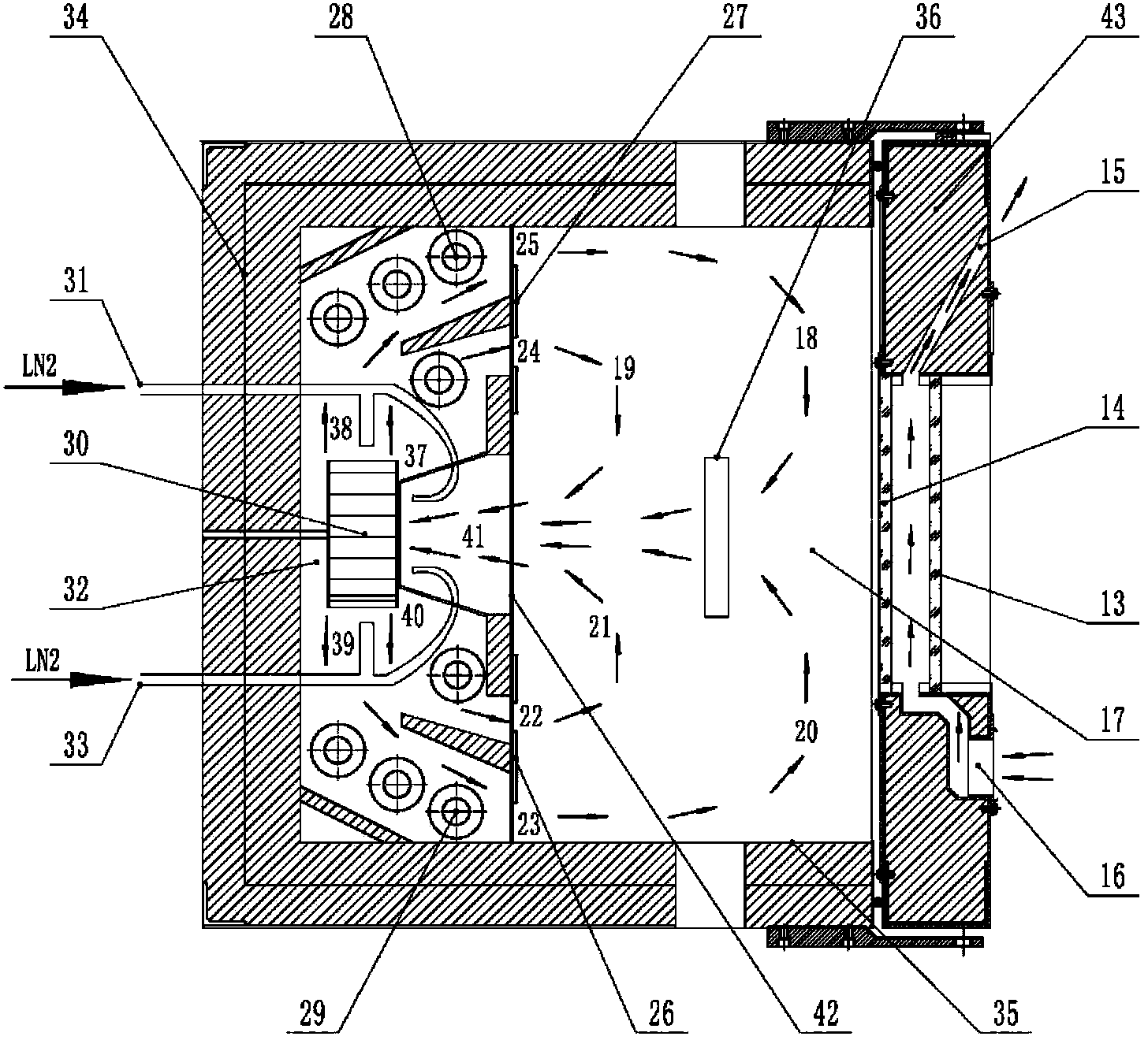
[0014] The structure, principle and specific implementation of the present invention will be further clearly and completely described below in conjunction with the accompanying drawings. figure 1 It is a schematic diagram of the overall structure of the high and low temperature dynamic cooling and heating cycle thermodynamics test system. The system includes a test chamber 1, a lighting system in the chamber, a liquid nitrogen refrigeration system, an observation window and a system control cabinet. The test chamber 1 is divided into an inner chamber by an inner and outer partition The body 32 and the outer cavity 17, the inner cavity 32 contains heating wires and wind-stirring turbines, and the separator is provided with an air outlet and an air suction port; the test system also includes a dual-output PID controller and a DIC full-field strain measuring instrument; The liquid nitrogen refrigeration system described above adopts a self-switching liquid nitrogen refrigeration s...


PUM


Abstract

The invention discloses a high-low temperature dynamic cold-hot circulation thermodynamic test system suitable for mechanics performance testing under a high-low temperature environment. A test box adopts a design of an inner cavity and an outer cavity; inner and outer cavity baffles are provided with four air outlets from top down and air suction holes in the center; the test box further comprises an optical strain observation window, a defrosting air heater and a multi-point direct-current illumination source; and in addition, the test system further comprises a dual-output PID (Proportion Integration Differentiation) controller, a DIC (Digital Image Correlation) full strain measurement instrument and an automatic switchover liquid nitrogen refrigerating system. According to the high-low temperature dynamic cold-hot circulation thermodynamic test system, the defects that the conventional thermal steady state test system has no thermal transient state and thermal circulation functions and liquid nitrogen cannot be fed without interruption due to limitation of liquid nitrogen container volume on low-temperature refrigeration are solved, and the technical problems of interference and the like of high-temperature hot wave impact and low-temperature frost fog on full strain measurement are solved at the same time, so that the purposes of obtaining the mechanical performance of a test material under the high-low temperature environment in the processes of thermal steady state, thermal transient state, cold-hot circulation and the like and synchronously measuring a sample strain field are achieved.

Description

technical field [0001] The invention relates to a high-low temperature dynamic cold-heat cycle thermodynamic test system, which is suitable for testing mechanical properties of materials such as thermal steady state, thermal transient state, and cold-heat cycle in a high-low temperature environment, and can simultaneously measure the surface strain field of a sample. Background technique [0002] In the fields of aerospace, electronics, biology, machinery, etc., the complex service temperature environment puts forward high requirements on the mechanical properties of materials such as thermal stability, thermal cycle, and thermal fatigue. It exhibits unique thermodynamic response characteristics under the rate of change. Therefore, the transient mechanical response of materials under high and low temperature alternating action has always been a difficult point in the thermodynamic detection of materials. At present, the existing technology and related thermodynamic test prod...

Claims


Application Information

Patent Timeline
Patent Type & Authority Patents(China)
IPC IPC(8): G01N3/18G01N3/02
Inventor 杜泓飞曾攀雷丽萍
Owner TSINGHUA UNIV
Learn More