
Leakproof device for water storing container

A water storage container and anti-leakage technology, which is applied in the field of anti-leakage devices and anti-leakage devices for water storage containers, can solve the problems of complex structure, untimely alarm and cut-off control, and occupying too much space, and achieves simple connection. Convenience, avoid continuous leakage, high reliability effect

Inactive Publication Date: 2013-01-16
A O SMITH CHINA WATER HEATER CO LTD
View PDF2 Cites 3 Cited by
  • Summary
  • Abstract
  • Description
  • Claims
  • Application Information

AI Technical Summary

Problems solved by technology

[0004] The above-mentioned existing technologies all require the joint action of the detection and induction system, the signal processing system and the water inlet controller to cut off the water after leakage. If the control is not timely, if the reaction is too sensitive, it is prone to false alarms and malfunctions, and additional power supply is required, the structure is complicated, and it also brings troubles such as the need to prevent electric shocks and occupying too much space

Method used


Image

  • Leakproof device for water storing container
  • Leakproof device for water storing container
  • Leakproof device for water storing container

Examples


Embodiment 1

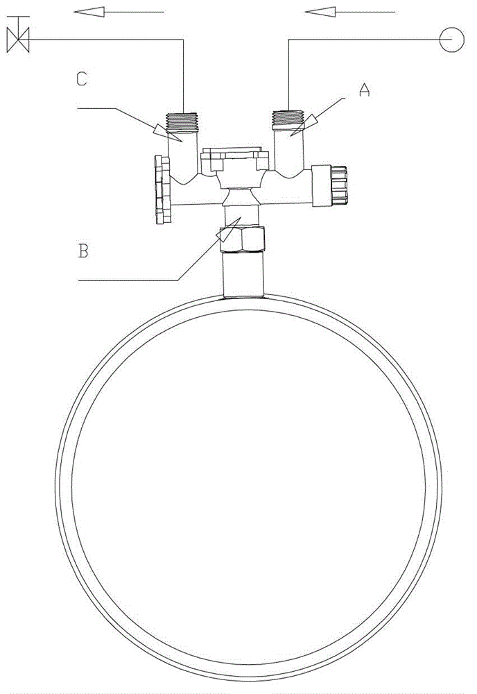
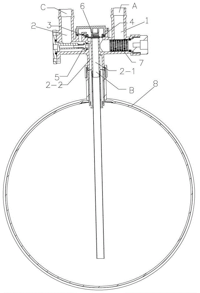
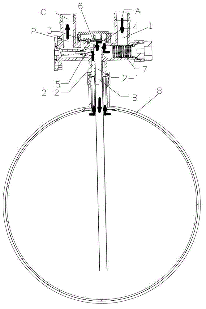
[0021] This embodiment is an anti-leakage device for an external water storage container applied to an electric water heater, such as figure 1 As shown, it includes a first port A for communicating with a tap water supply pipeline, a second port B for communicating with an electric water heater storage container (commonly known as an inner tank) 8 and a third port for communicating with the water end of the faucet C; The second port B is composed of a water inlet chamber and a water outlet chamber, and a water flow loop is formed between the outer wall of the water inlet chamber and the inner wall of the water outlet chamber. Between the first port A and the second port water inlet chamber is a first water flow channel 1, and between the second port water outlet chamber and the third port C is a second water flow channel 2. by figure 2 with image 3 It can be seen that the first water flow channel 1 between the first port A and the second port water inlet chamber is provided wi...

Embodiment 2

[0029] The anti-leakage device of the external water storage container of this embodiment is as Figure 4 As shown, the basic structure is the same as the first embodiment, the difference is that the water inlet chamber and the water outlet chamber are respectively composed of a water inlet pipe 2-1 and a water outlet pipe 2-2, and the water inlet pipe 2-1 and the water outlet pipe 2-2 They are separated by a partition board 9. The effect is the same as that of the first embodiment, and will not be described in detail.


PUM


Abstract

The invention relates to a leakproof device for a water storing container, belonging to the technical field of the control of a fluid transportation pipeline. The device comprises a first port communicated with a water supply pipeline, a second port communicated with the water storing container, and a third port communicated with a water use end. The leakproof device is characterized in that the second port is formed by a water inlet cavity and a water outlet cavity, which are separated form each other; a first water flowing passageway arranged between the first port and the water inlet cavity of the second port is provided with a on-off controller, and the water outlet cavity is communicated with the third port by a second water flowing passageway; when the water use end is turned off, the on-off controller is under the status of switching off the first water flowing passageway; and when the water use end is turned on, the on-off controller is under the status of switching on the first water flowing passageway. Therefore, when the water use end is turned off and users does not need to use water, the first water flowing passageway is turned off, and even if the water storing container leaks, the water of a water source can not be compensated to the water storing container, so that the continuous leakage can be effectively avoided no matter whether the leakage is known by the user or not.

Description

Technical field [0001] The invention relates to an anti-leakage device, in particular to an anti-leakage device for a water storage container, which belongs to the technical field of fluid transport pipeline control. Background technique [0002] According to the applicant’s understanding, water storage containers such as storage-type electric water heaters will undergo oxygen and hydrogen evolution reactions due to the effect of galvanic batteries, resulting in corrosion. Even if the surface is painted, the anode rod is added, or the stainless steel material is used to delay corrosion, it is still inevitable that corrosion perforation will cause leakage. When the leakage occurs, if the user does not know, the leakage will continue because the existing water storage container is connected to the water source, causing a large area of ​​flooding and causing losses. [0003] In order to solve this problem, the Chinese utility model with application number 200820006351.3 discloses an ...

Claims


Application Information

Patent Timeline
IPC IPC(8): F24H9/20
CPCF24H9/136
Inventor 万华新邵小荣茹兴鹏
Owner A O SMITH CHINA WATER HEATER CO LTD
Learn More