
Method for measuring aberration of imaging system based on lateral shearing interference structure

A technology of transverse shearing and imaging system, which is applied in the field of optical inspection, and can solve the problems of increased reconstruction error, poor linearity, and increased aberration measurement error of the imaging system, etc.

Active Publication Date: 2013-01-09
SHANGHAI INST OF OPTICS & FINE MECHANICS CHINESE ACAD OF SCI
View PDF6 Cites 21 Cited by
  • Summary
  • Abstract
  • Description
  • Claims
  • Application Information

AI Technical Summary

Problems solved by technology

These initial values ​​are obtained by linear interpolation of the differential wavefront, and the linear interpolation is based on the linearity assumption of the wavefront to be measured, that is, the wavefront to be measured is at S y ×S x The linear change in the rectangular grid, this assumption is approximately true when the shear amount is relatively small, in this case the wavefront can be reconstructed with higher accuracy, but the linearity of the wavefront in the rectangular grid when the shear amount becomes larger becomes worse, the wavefront reconstruction error increases significantly, which makes the aberration measurement error of the imaging system significantly increase

Method used


Image

  • Method for measuring aberration of imaging system based on lateral shearing interference structure
  • Method for measuring aberration of imaging system based on lateral shearing interference structure
  • Method for measuring aberration of imaging system based on lateral shearing interference structure

Examples


Embodiment Construction

[0054] The present invention will be further described below in conjunction with the embodiments and accompanying drawings, but the protection scope of the present invention should not be limited thereby.

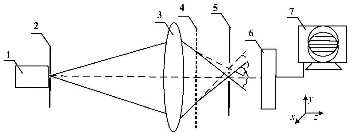
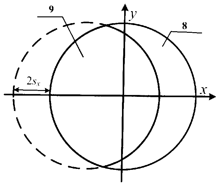
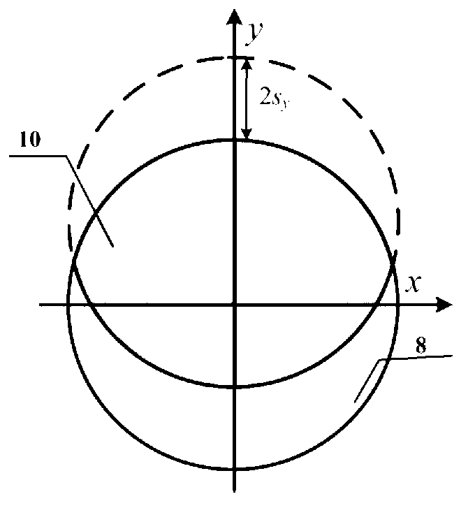
[0055] see first figure 1 and Figure 9 , figure 1 figure 1 It is a schematic diagram of the aberration measurement system of the imaging system based on the transverse shear interference structure used in the present invention, Figure 9 It is a flow chart of the method for measuring the aberration of the imaging system based on the transverse shear interference structure of the present invention. It can be seen from the figure that the present invention is based on the measurement method of the aberration of the imaging system based on the transverse shear interference structure. The measurement system adopted in this embodiment includes a light source 1, and the direction of the light beam output along the light source 1 is pinhole mask 2, shear Grating 4, double-win...


PUM


Abstract

The invention discloses a method for measuring the aberration of an imaging system based on a lateral shearing interference structure. A measurement system comprises a light source, a pinhole mask, a shearing grating, a dual-window mask, a photoelectric detector and a computer. During measurement, the imaging system to be measured is arranged between the pinhole mask and the shearing grating. The method comprises the following steps of: (1) acquiring lateral shearing interferograms in directions x and y; (2) acquiring differential wavefronts in the directions x and y; (3) reconstructing the wavefronts by utilizing a modal method, and acquiring an initial value for zonal construction; and (4) reconstructing the wavefronts by utilizing a zonal method, and acquiring the aberration of the imaging system to be measured. The high-spatial resolution lateral shearing measurement of the aberration of the imaging system is realized on the basis of no increase of measurement times, and the measurement accuracy is insensitive to a change in shear, namely a wavefront measurement error is not remarkably increased along with the increase of the shear.

Description

technical field [0001] The invention belongs to the technical field of optical detection, and in particular relates to a method for measuring the aberration of an imaging system based on a transverse shear interference structure. Background technique [0002] In recent years, transverse shearing interferometry has been widely used and developed in the field of wavefront aberration measurement of optical imaging systems. Its main advantage is that the wavefront interferes with itself, no additional reference wavefront is required, and measurement errors introduced by the reference wavefront are eliminated. In addition, the transverse shear interference is equal optical path interference, so it is not sensitive to mechanical vibration and environmental disturbance. The disadvantage of transverse shear interference is that the phase extracted from the interferogram directly reflects the differential information of the wavefront (differential wavefront), rather than the wavefro...

Claims


Application Information

Patent Timeline
IPC IPC(8): G01M11/02G01J9/02
Inventor 戴凤钊唐锋王向朝张敏
Owner SHANGHAI INST OF OPTICS & FINE MECHANICS CHINESE ACAD OF SCI
Learn More