
Energy-saving gas stove

A stove and gas technology, which is applied to heating fuels, household stoves/stoves, gaseous heating fuels, etc., can solve the problems of rising use costs, low combustion completeness, indurability, etc., and achieves simple and convenient maintenance and use, improved thermal efficiency, Easy ignition effect

Inactive Publication Date: 2013-01-09
郭明魁
View PDF4 Cites 3 Cited by
  • Summary
  • Abstract
  • Description
  • Claims
  • Application Information

AI Technical Summary

Problems solved by technology

[0002] Green and environmental protection, low-carbon life is a brand-new way of life advocated by countries all over the world. The excessive exploitation and abuse of earth resources have led to the depletion of resources and the gradual increase in use costs. Energy conservation and emission reduction have become the concern and support of the country and governments at all levels. Environmental protection projects, in the catering industry, the heat utilization rate of stoves is less than 20%, resulting in a lot of energy waste
At present, the traditional commercial cooker products widely used in China have many disadvantages such as high energy consumption, high pollution, low efficiency, unsafe, not durable, difficult maintenance, and complicated operation.
[0003] At present, energy saving and emission reduction has become the goal pursued by every energy-consuming unit, especially the energy saving and emission reduction of gas cookers has great economic and social benefits. The gas and air mixing forms of the gas cooker can be divided into internal mixing and external mixing structures. The internal mixing gas cooker is more efficient than the external mixing gas cooker, but there are also problems such as uneven mixing and small fire combustion. Insufficient and other problems, in short, the combustion completeness of the internal mixing gas cooker is still low, and there is still room for improvement

Method used


Image

  • Energy-saving gas stove
  • Energy-saving gas stove
  • Energy-saving gas stove

Examples


Embodiment Construction

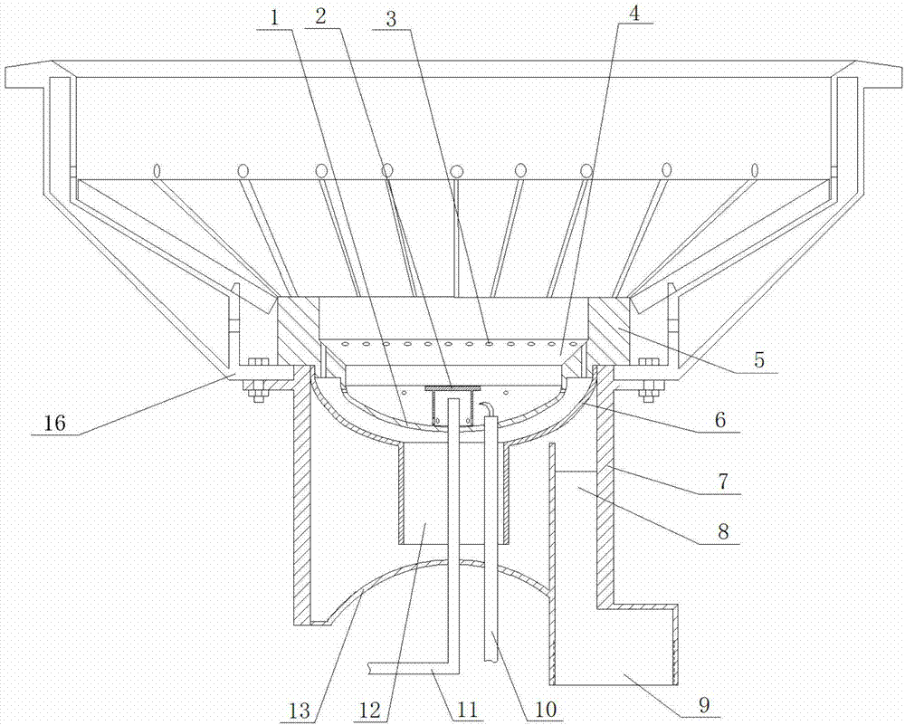
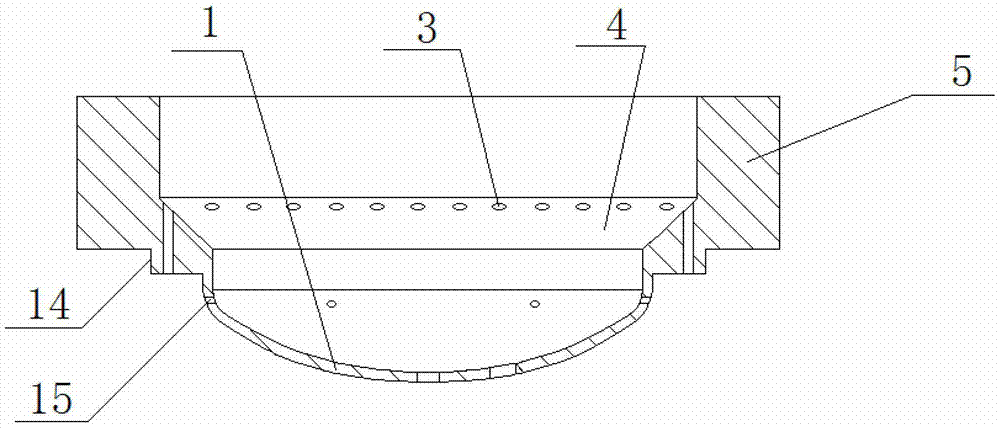
[0022] Such as figure 1 and figure 2 As shown, an energy-saving gas cooker head includes a furnace 16, a flame nozzle 5, an open flame cover 2, an open flame mixing gas pipe 11 and an ignition wire 10; Guide cover 6 and gas mixing chamber 7 positioned under the guide cover;

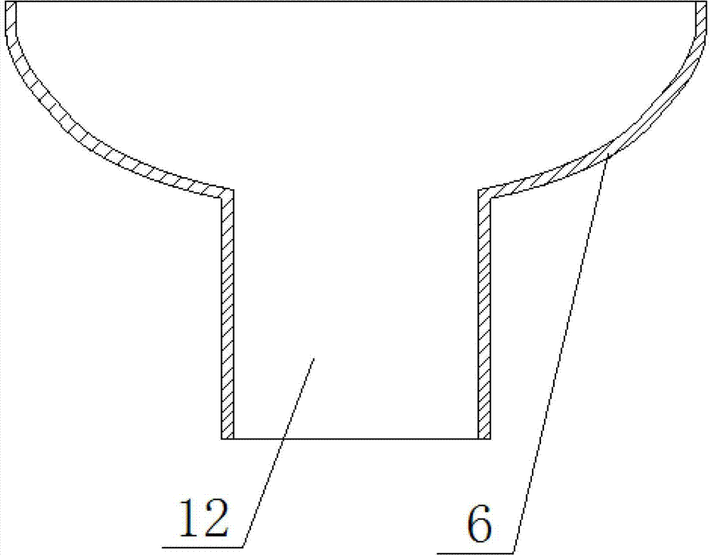
[0023] Such as image 3 As shown, the upper part of the guide cover 6 is a concave spherical surface, and the lower part is a tubular guide cover tube 12, and the upper opening communicates with the lower part;

[0024] Such as figure 1 and figure 2 As shown, the fire nozzle 5 is located at the middle and lower part of the hearth 16, and its upper part is tubular, and the lower part of the tube is provided with an inclined plane boss 4 along the circumferential direction, and the inclined fire nozzle 3 is arranged on the inclined plane boss. Concave spherical surface 1, a number of combustion-supporting fire injection holes 15 are distributed along the circumferential direction on the side of the c...


PUM


Abstract

The invention provides an energy-saving gas stove and belongs to the technical field of gas cooking appliances. The gas stove mainly solves the problems that mixture gas is not mixed uniformly, the low flame combustion is not sufficient and the thermal efficiency is low. The gas stove mainly comprises a hearth, a flaming head, a normally-open fire hood, a normally-open fire mixture gas pipe and an ignition wire and is characterized by also comprising a guide cover and a gas mixing chamber, wherein the guide cover is in interference fit with a boss under the flaming head, the gas mixing chamber is located below the guide cover, the bottom of the flaming head is in a concave spherical surface shape, the upper portion of the guide cover is also a concave spherical surface, the bottom of the gas mixing chamber is a convex spherical surface, the structure guarantees that the mixture gas is mixed uniformly, a combustion-supporting flaming hole which is arranged on the side face of the concave spherical surface of the flaming head guarantees the ignition of a main flame, the combustion is stable during low flame, and the thermal efficiency is high.

Description

technical field [0001] The invention belongs to the technical field of gas stoves, and in particular relates to an energy-saving gas stove head. Background technique [0002] Green and environmental protection, low-carbon life is a brand-new way of life advocated by countries all over the world. The excessive exploitation and abuse of earth resources have led to the depletion of resources and the gradual increase in use costs. Energy conservation and emission reduction have become the concern and support of the country and governments at all levels. Environmental protection projects, in the catering industry, the heat utilization rate of stoves is less than 20%, resulting in a lot of energy waste. At present, the traditional commercial cooker products widely used in China have many disadvantages such as high energy consumption, high pollution, low efficiency, unsafe, not durable, difficult maintenance, and complicated operation. [0003] At present, energy saving and emissi...

Claims


Application Information

Patent Timeline
Patent Type & Authority Applications(China)
IPC IPC(8): F24C3/08
Inventor 郭明魁
Owner 郭明魁
Learn More