
Dust removal device and dust removal method for high-temperature flue gas

A dust removal device and high-temperature flue gas technology, applied in the direction of combination devices, separation methods, chemical instruments and methods, etc., can solve the problems of vacuum pump damage, reduced lubrication function, carbonization of engine oil, etc., to improve dust removal efficiency, reduce flue gas temperature, Avoid the effect of carbonation

Active Publication Date: 2014-12-24
PANZHIHUA IRON & STEEL RES INST OF PANGANG GROUP
View PDF3 Cites 0 Cited by
  • Summary
  • Abstract
  • Description
  • Claims
  • Application Information

AI Technical Summary

Problems solved by technology

In the process of use, it was found that this device has a lot of defects. First, the temperature of the exhaust gas is relatively high (700-900 ° C), and the direct dust removal operation can easily cause carbonization of the engine oil. Not only can it not absorb dust particles, but it will cause carbonization The carbon particles enter the vacuum pump, pollute the pump oil, reduce its lubricating function, and cause great damage to the vacuum pump

Method used


Image

  • Dust removal device and dust removal method for high-temperature flue gas
  • Dust removal device and dust removal method for high-temperature flue gas

Examples


Embodiment Construction

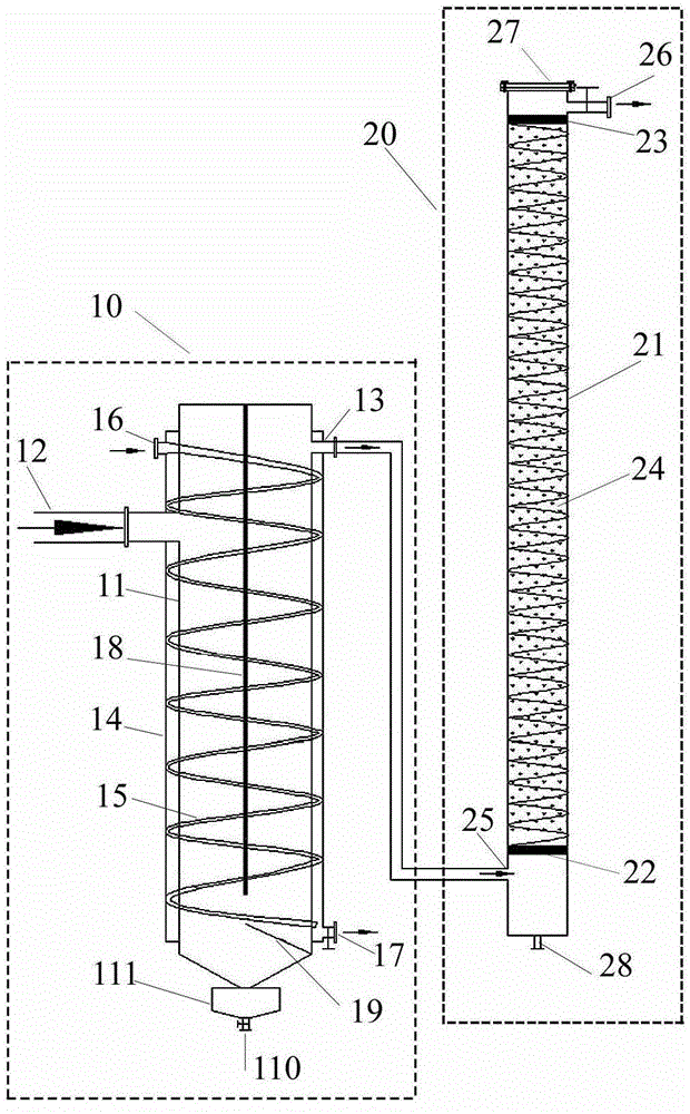
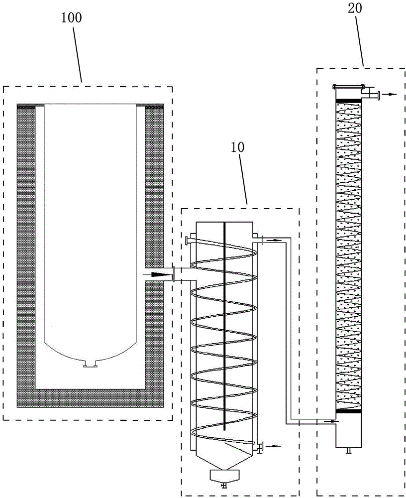
[0019] The high-temperature flue gas dedusting device and method according to the present invention will be described in detail below with reference to the accompanying drawings and exemplary embodiments.

[0020] figure 1 is a schematic diagram of a high-temperature flue gas dedusting device according to an exemplary embodiment of the present invention. figure 2 It is a schematic diagram of a high-temperature flue gas dedusting device connected with a vacuum distillation device (for example, a sponge titanium distillation furnace, referred to as a distillation furnace) according to an exemplary embodiment of the present invention. Such as figure 1 As shown, the high-temperature flue gas dust removal device of this exemplary embodiment includes a first dust removal system 10 and a second dust removal system 20 .

[0021] The first dust removal system includes: a cylindrical first cylinder 11, a flue gas inlet 12 and a flue gas outlet 13 communicated with the inside of the f...


PUM

PropertyMeasurementUnit
thicknessaaaaaaaaaa
thicknessaaaaaaaaaa

Abstract

The invention provides a dust removal device and a dust removal method for high-temperature flue gas. The dust removal device comprises a first dust removal system and a second dust removal system; the first dust removal system comprises a first barrel, a flue gas inlet, a flue gas outlet and a cooling water component, the flue gas inlet and the flue gas outlet are communicated with the inside of the first barrel, and the cooling water component encircles the first barrel and cools down the first barrel; and the second dust removal system comprises a second barrel, an engine-oil dust removal component, a flue gas inlet and a flue gas outlet, the engine-oil dust removal component is arranged in the second barrel and consists of a base and engine oil attached on the surface of the base, the flue gas inlet is arranged on the lower side of the base, the flue gas outlet is arranged on the upper side of the base, and the flue gas outlet of the first dust removal system is communicated with the flue gas inlet of the second dust removal system. The dust removal method includes cooling the flue gas and removing dust from the flue gas by gravity simultaneously; removing dust by the engine oil; and feeding the flue gas of which the dust is removed by the engine oil into a vacuum system. Power of the flue gas is supplied by the vacuum system. By the dust removal device, the temperature of the flue gas is reduced, the dust removal engine oil is prevented from being carbonized, and the dust removal efficiency is greatly improved.

Description

technical field [0001] The invention relates to the technical field of dedusting high-temperature gas powered by a vacuum system, and more specifically, relates to a device and method for dedusting high-temperature gas in the inner cavity of a sponge titanium distillation electric furnace extracted by a vacuum system. Background technique [0002] When using the magnesia thermal reduction method to produce sponge titanium, in order to shorten the distillation time and reduce the energy consumption of distillation, the method of vacuum distillation is used in the production. The internal vacuum treatment is called anti-vacuum operation. Because there are many fine refractory particles in the distillation furnace, refractory particles will be mixed in the flue gas of the distillation furnace. These solid particles will greatly damage the vacuum pump and easily affect the vacuum degree of the system. Therefore, before entering the vacuum pump, it is necessary to Dust removal o...

Claims


Application Information

Patent Timeline
Patent Type & Authority Patents(China)
IPC IPC(8): B01D50/00B01D45/02B01D47/00
Inventor 苗庆东李开华杨仰军程晓哲张继东
Owner PANZHIHUA IRON & STEEL RES INST OF PANGANG GROUP
Learn More