
Electric connector capable of being electromagnetically unlocked and assembly of electric connector

An electrical connector and unlocking technology, which is applied to the parts, connections, electrical components and other directions of the connecting device, can solve the problem that the electrical connector cannot be separated reliably.

Inactive Publication Date: 2013-01-02
CHINA AVIATION OPTICAL-ELECTRICAL TECH CO LTD
View PDF3 Cites 5 Cited by
  • Summary
  • Abstract
  • Description
  • Claims
  • Application Information

AI Technical Summary

Problems solved by technology

[0005] The purpose of the present invention is to provide an electromagnetic unlocking electrical connector to solve the problem that the existing electromagnetic unlocking electrical connector cannot be reliably separated under heavy load

Method used


Image

  • Electric connector capable of being electromagnetically unlocked and assembly of electric connector
  • Electric connector capable of being electromagnetically unlocked and assembly of electric connector
  • Electric connector capable of being electromagnetically unlocked and assembly of electric connector

Examples


Embodiment Construction

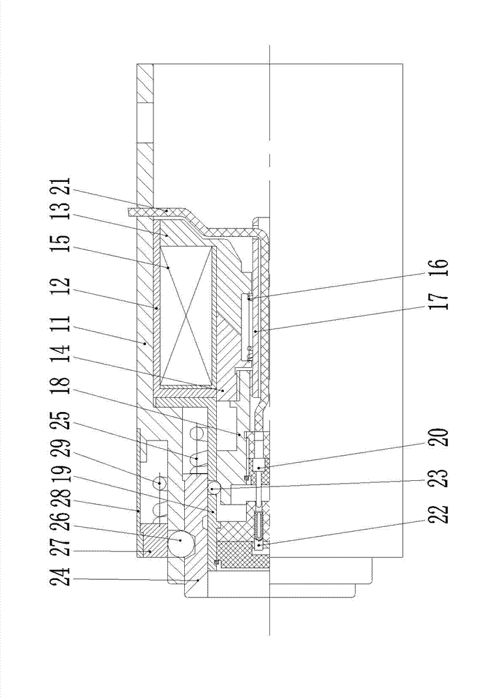
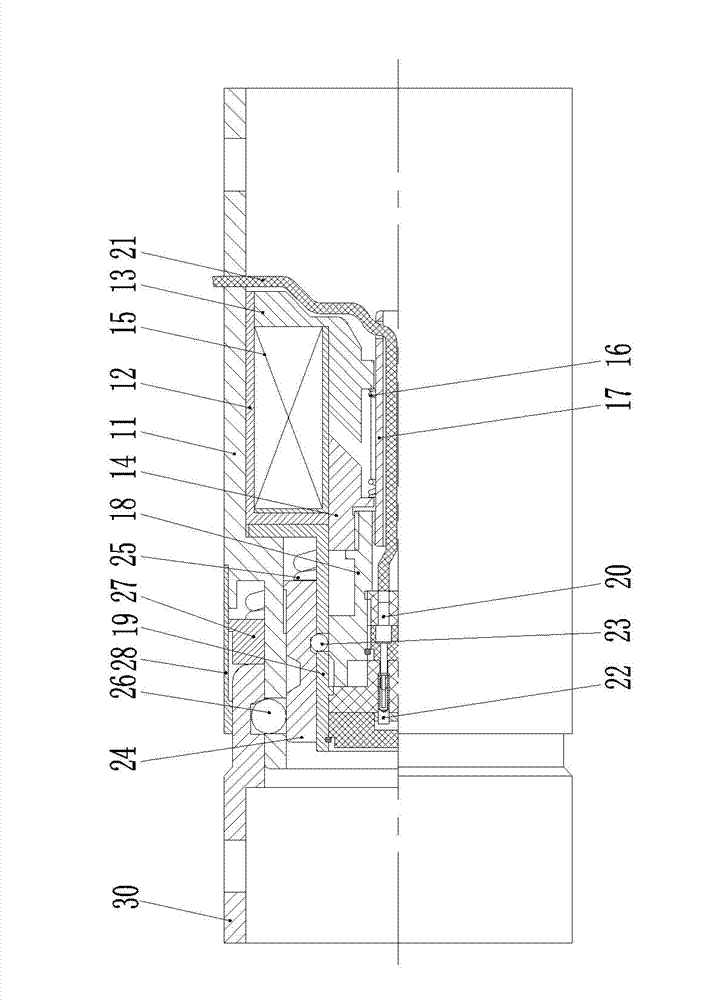
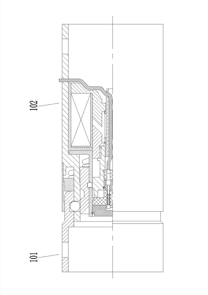
[0021] Embodiment 1 of the electromagnetic unlocking electrical connector of the present invention, such as Figure 1-2As shown, it includes housing 11, electromagnetic mechanism, center spring 16, wire inlet sleeve 17, center lock sleeve 18, seat cover 19, needle contact 20, wire 21, hole contact 22, inner steel ball 23, middle lock Cover 24, energy storage spring 25, outer layer steel ball 26, outer layer locking sleeve 27 and pushing spring 29. The housing 11 is in the shape of a stepped sleeve, including a small-diameter section at the front end and a large-diameter section at the rear end, and its inner hole also includes a small-diameter section at the front end and a large-diameter section at the rear end. The electromagnetic mechanism is fixedly assembled on the large-diameter section of the inner hole of the housing In the section, including the shell 12, the fixed armature 13 assembled in the shell 12, the movable armature 14, and the electromagnetic coil 15, the fix...


PUM


Abstract

The invention relates to the field of electric connectors, in particular to an electric connector capable of being electromagnetically unlocked and an assembly of the electric connector. The front end of the electric connector is a plug end, in an initial state, an outer-layer lock sleeve is located at the periphery of an outer-layer steel ball, the outer-layer steel ball is protruded out of the inner-layer sidewall of a housing and locked inside a groove on the outer-layer wall of a middle lock sleeve, the middle lock sleeve is locked by the outer-layer steel ball, and the inner-layer steel ball is protruded out of the inner-layer sidewall of a socket sleeve and matched with a stepped surface formed between a large-diameter section and a small-diameter section at the front part of the middle lock sleeve so as to prevent the middle lock sleeve from moving forwards; and the outer-layer lock sleeve is pushed backwards by a lock sleeve on an adapter connector when being locked with the adapter connector, so that the outer-layer steel ball is protruded to the periphery of the housing, the groove on the inner-layer wall of the middle lock sleeve is moved to the periphery of the inner-layer steel ball, the middle lock sleeve is moved forwards so as to push the inner-layer steel ball through the large-diameter section at the front part of the middle lock sleeve, and the inner-layer steel ball is protruded out of the socket sleeve and locked into the groove on the inner-layer wall of the middle lock sleeve. The problem that the existing electric connector capable of being electromagnetically unlocked cannot be reliably separated in a heavy load is solved.

Description

technical field [0001] The invention relates to the field of electrical connectors, in particular to an electromagnetic unlocking electrical connector and components thereof. Background technique [0002] In some occasions, it is required that the plug and socket of the electrical connector assembly can be separated automatically, and at this time, an electrical connector with electromagnetic unlocking is often used. [0003] Assuming that the front end is used as the plug-in end, the electromagnetically unlocked electrical connector includes a housing in which a locking mechanism, an insulator and a contact are assembled. The locking mechanism includes an outer sleeve, a core sleeve, a lock shaft, a sliding sleeve, Pushing spring and locking spring; the outer casing is fixedly assembled in the housing and the extension direction of its center line is the same as the insertion direction of the connector. The core sleeve is coaxially arranged in the outer sleeve and fixed wit...

Claims


Application Information

Patent Timeline
Patent Type & Authority Applications(China)
IPC IPC(8): H01R13/633H01R13/635H01R13/639H01R24/00
Inventor 陈继利卞书波
Owner CHINA AVIATION OPTICAL-ELECTRICAL TECH CO LTD
Learn More