
A high-brightness LED optical axis detection device and detection method for optical axis offset

A technology of optical axis offset and detection method, applied in the direction of testing optical performance, etc., can solve problems such as troublesome LED selection, and achieve the effect of solving troublesome LED selection, reasonable design, and intuitive display of screening results.

Inactive Publication Date: 2015-08-12
GUANGDONG UNIV OF TECH
View PDF5 Cites 0 Cited by
  • Summary
  • Abstract
  • Description
  • Claims
  • Application Information

AI Technical Summary

Problems solved by technology

The invention can solve the troublesome problem of selecting LEDs in industrial production or special applications

Method used


Image

  • A high-brightness LED optical axis detection device and detection method for optical axis offset
  • A high-brightness LED optical axis detection device and detection method for optical axis offset
  • A high-brightness LED optical axis detection device and detection method for optical axis offset

Examples


Embodiment Construction

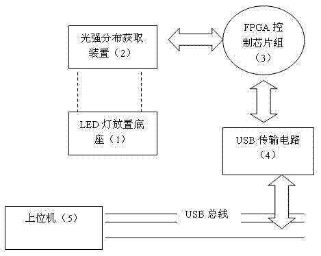
[0026] The principle diagram of the high-brightness LED optical axis detection device of the present invention is as follows figure 1 As shown, it includes an LED lamp placement base 1 for installing high-brightness LEDs, a light intensity distribution acquisition device 2, an FPGA control chipset 3, a USB transmission circuit 4, and a host computer 5, wherein the light intensity distribution acquisition device 2 is installed on The LED lamp is placed on the side of the base 1 and at a position where high-brightness LED light intensity can be obtained, the FPGA control chipset 3 drives the light intensity distribution acquisition device 2 to obtain the image data of the LED light intensity distribution, and the FPGA control chipset 3 passes through the USB The transmission circuit 4 uploads the collected data to the host computer 5 in real time. The above-mentioned light intensity distribution acquiring device 2 is a CCD chipset.

[0027] The positions of the high-brightness ...


PUM


Abstract

The invention relates to an optical path detector for high-brightness LEDs and a detection method of optical axis deviation in high-brightness LEDs. The detector comprises an LED holder, a light intensity acquisition device, a FPGA (field programmable gate array) control chip set, a USB (universal serial bus) transmission circuit and an upper computer, wherein the LED holder is used for fitting a high-brightness LED, the light intensity acquisition device is disposed on the side of the LED holder and is capable of acquiring the position of light intensity of the high-brightness LED, the FPGA control chip set drives the light intensity acquisition device to acquire distribution image data of light intensity of the LED, and the FPGA control chip set uploads the acquired data to the upper computer through the USB transmission circuit in real time. The detection method of optical axis deviation in high-brightness LEDs includes the steps: firstly, acquiring distribution image data of direct light intensity of the high-brightness LED; and secondly, processing the light intensity data, and analyzing deviation of LED optical axis. The optical path detector for high-brightness LEDs and the detection method of optical axis deviation in high-brightness LEDs are applicable to selection of LED lights having special requirements for optical axis of high-brightness LED lights. The detector is simple to operate and reliable in performance, and screening results are displayed visually.

Description

technical field [0001] The invention relates to a high-brightness LED optical axis detection device and an optical axis offset detection method, belonging to the technical field of photoelectric testing. Background technique [0002] LED is a light-emitting system composed of LED chips and lenses with a certain curvature radius. For example, in quantitative detection sensors, the light output characteristics of LED light-emitting diodes should be used to make the photoelectric sensors made with high sensitivity. It is very important to make the optical axis of the LED coincide with the mechanical axis of the lens system. to get a larger output. In addition, some occasions may require that the optical axis of the LED lamp has a certain angle of offset (polarization axis LED tube), such as a display screen. Such a display screen can reduce the LED current when obtaining the same light intensity. In reality has a certain meaning. Therefore it is necessary to measure its opti...

Claims


Application Information

Patent Timeline
Patent Type & Authority Patents(China)
IPC IPC(8): G01M11/02
Inventor 张灵朱振峰
Owner GUANGDONG UNIV OF TECH
Learn More