
Trimming, flanging and side punching compound die

A composite mold, side punching technology, applied in forming tools, manufacturing tools, metal processing equipment, etc., can solve problems such as positioning deviation, affecting product quality, and large vibration and impact, avoiding excessive contact or collision, and improving inspection judgment. The effect of high speed and workpiece machining accuracy

Active Publication Date: 2013-01-02
JIANGSU RONGTENG PRECISION COMPONENTS
View PDF12 Cites 15 Cited by
  • Summary
  • Abstract
  • Description
  • Claims
  • Application Information

AI Technical Summary

Problems solved by technology

[0002] Trimming, flanging, and punching processes are widely used in the processing and production of automobile sheet metal parts. The traditional processing method is to use trimming, flanging, and punching molds respectively. The number of molds required is large, and the cost of molds is high. Production Low efficiency, and the use of several sets of molds for multiple clamping of materials and multiple positioning results in product positioning deviations between different processes, resulting in product processing errors and affecting product quality
Moreover, these traditional trimming, flanging, and punching dies have a large vibration and impact during work, which generates noise and vibration, which has a great impact on the working life of the die, and it is inconvenient to check the die test, and it is not easy to judge the die processing Effect

Method used


Image

  • Trimming, flanging and side punching compound die
  • Trimming, flanging and side punching compound die
  • Trimming, flanging and side punching compound die

Examples


Embodiment Construction

[0023] The present invention will be described in detail below in conjunction with accompanying drawings and specific preferred embodiments, so that the advantages and features of the present invention can be more easily understood by those skilled in the art. range is limited.

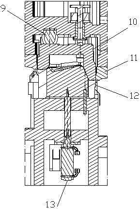
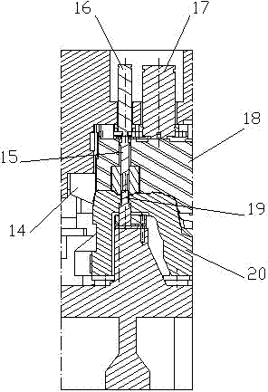
[0024] see Figure 1 to Figure 6 , the trimming and flanging side punching composite mold of the present invention comprises: upper mold 1 and lower mold 2, described upper mold 1 is positioned at described lower mold 2 top, and described upper mold 1 is provided with a plurality of guide sleeves 31, trimming Upper die 3, flanging upper die 4 and side punching upper die 5, described lower die 2 is provided with a plurality of guide pillars 30, a plurality of stop blocks 25, a plurality of nitrogen springs 26, a plurality of wear plates 27, repair Limit lower die 6, flanging lower die 7 and side punching lower die 8, described trimming upper die 3 is provided with Youli glue 9, binder plate 10 and upp...


PUM


Abstract

The invention discloses a trimming, flanging and side punching compound die which comprises an upper die and a lower die, wherein the upper die is provided with a trimming upper die, a flanging upper die and a side punching upper die; the lower die is provided with a nitrogen spring, a trimming lower die, a flanging lower die and a side punching lower die; the trimming upper die is provided with casting polyurethane, a pressing plate and an upper die trimming block; the trimming lower die is provided with a lower die trimming block and a cylinder ejection mechanism; the flanging upper die is provided with a concave die, a flanging block, a stripping mechanism, a stripping nitrogen cylinder, a pressing plate nitrogen cylinder, an upper die pressing plate and a hole flanging punch; the flanging lower die is provided with a convex die, a setting gage and a lower die pressing plate; and the side punching upper die is provided with a side punching punch, a polyester cyanamide pressing mechanism, a slide wedge and a roller wheel. By using the mode of the compound die, several processing procedures of trimming, flanging and side punching of workpieces made of metal plates can be completed through one set of die, once feeding is performed, the processing accuracy of the workpieces is high, the production efficiency is high, and the die cost is saved.

Description

technical field [0001] The invention relates to a metal plate part processing die, in particular to a composite die for trimming, flanging and side punching. Background technique [0002] Trimming, flanging, and punching processes are widely used in the processing and production of automobile sheet metal parts. The traditional processing method is to use trimming, flanging, and punching molds respectively. The number of molds required is large, and the cost of molds is high. Production The efficiency is low, and the use of several sets of molds for multiple clamping of materials and multiple positioning results in product positioning deviations between different processes, resulting in product processing errors and affecting product quality. Moreover, these traditional trimming, flanging, and punching dies have a large vibration and impact during work, which generates noise and vibration, which has a great impact on the working life of the die, and it is inconvenient to chec...

Claims


Application Information

Patent Timeline
Patent Type & Authority Applications(China)
IPC IPC(8): B21D37/10
Inventor 杨荣
Owner JIANGSU RONGTENG PRECISION COMPONENTS
Learn More