
Reel-up system and reel-up method thereof

A wire rod and winding reel technology, applied in the wire take-up system and its take-up field, can solve the problems of unreachable take-up tightness, poor size, hardening, etc., and achieve the effect of good take-up effect and high productivity

Inactive Publication Date: 2012-12-26
SUZHOU YOURBEST NEW TYPE MATERIALS
View PDF4 Cites 18 Cited by
  • Summary
  • Abstract
  • Description
  • Claims
  • Application Information

AI Technical Summary

Problems solved by technology

Before the existing wire take-up device takes up the wire, the width of the winding area of ​​the winding reel is usually measured manually with a scale, and the measured value is manually input into the PLC controller, and then the machine is turned on to carry out the winding operation. It can be seen that the automation length is relatively low; in addition, during the winding process, the winding diameter of the winding reel will continue to increase, causing the tension on the welding ribbon to also increase, so that the satisfactory tightness of the winding can not be achieved.
If it is too loose, due to the bumps on the road during the transportation of the ribbon coil, the winding on the ribbon coil will be arranged irregularly, which will bring many difficulties to the next process.
If it is too tight, it will lead to deformation, whitening, stretching, hardening, and poor size of the welding ribbon during the winding process. Therefore, the existing wire take-up device still has the problem of poor wire take-up effect

Method used

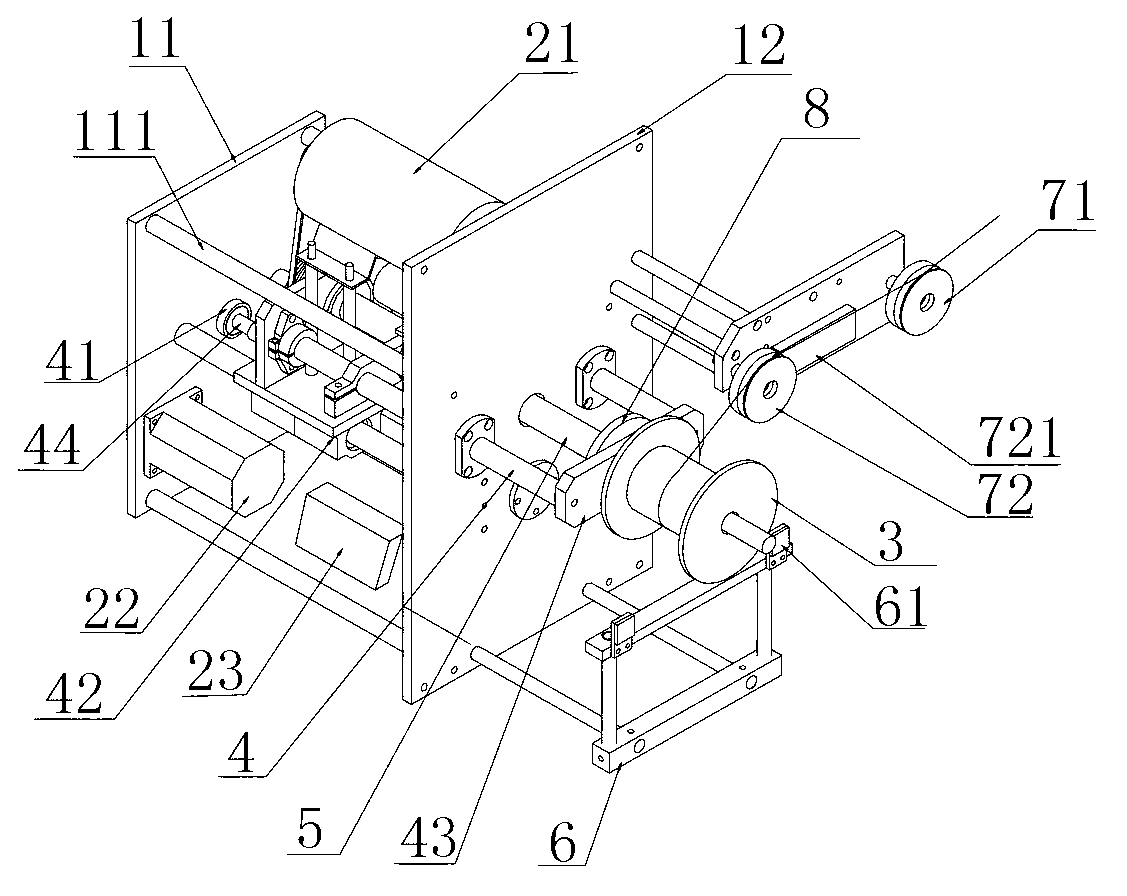

Image

  • Reel-up system and reel-up method thereof

Examples


Embodiment Construction

[0015] The following will clearly and completely describe the technical solutions in the embodiments of the present invention with reference to the drawings in the embodiments of the present invention.

[0016] A take-up system provided by the present invention includes a take-up unit; refer to figure 1 , the take-up unit includes a winding frame, a DC motor 21, a winding reel 3, a servo motor 22, and a PLC controller 23; the winding frame includes a left vertical plate 11 and a right vertical plate 12, and the left vertical plate 11 and the right vertical plate 12 are connected by connecting rod 111; DC motor 21 is located between left vertical plate 11 and right vertical plate 12, and DC motor 21 is connected with a reel 5, and reel 5 passes through right vertical plate 12 and is connected with winding reel 3; The inner side of the winding reel 3 is provided with a connecting plate 43, and the center of the connecting plate 43 is provided with a round hole (not shown in the ...


PUM


Abstract

The invention discloses a reel-up system and a reel-up method thereof. The reel-up system comprises a plurality of reel-up units, and each reel-up unit comprises a reel, a direct current motor, a wire spool, a servo motor and a PLC (Programmable Logic Controller) controller, wherein each reel comprises a left upright plate and a right upright plate, and the direct current motor is arranged between the left upright plate and the right upright plate and connected with a winding shaft which is connected with the wire spool; the inner side of each wire spool is provided with a connecting plate, the center of the connecting plate is provided with a round hole, and both ends of the connecting plate are respectively provided with a wire swing rod; the round hole is sleeved on the winding shaft; the wire swing rod passes through the right upright plate, and the tail end of the wire swing rod is respectively connected with a screw rod; the outer side of each screw rod is connected with a belt pulley, and the belt pulley is connected with the servo motor; an L-shaped rack is arranged below the reel, and the top of the L-shape rack is provided with an infrared photoelectric sensor; and one side of each reel is provided with two guide wheels, and the guide wheel close to the reel is connected with a gravity sensor. The reel-up system provided by the invention has the advantages of good reel-up effect and high productivity.

Description

technical field [0001] The invention relates to a wire take-up system and a wire take-up method. Background technique [0002] After each process of processing photovoltaic ribbons, it is usually necessary to take up the ribbons. Before the existing wire take-up device takes up the wire, the width of the winding area of ​​the winding reel is usually measured manually with a scale, and the measured value is manually input into the PLC controller, and then the machine is turned on to carry out the winding operation. It can be seen that the automation length is relatively low; in addition, during the winding process, the winding diameter of the winding reel will continue to increase, causing the tension on the welding ribbon to also increase, so that the satisfactory tightness of the winding cannot be achieved. If it is too loose, in the process of transporting the ribbon roll, due to the bumps on the road, the winding wires on the ribbon roll will be arranged irregularly, whi...

Claims


Application Information

Patent Timeline
Patent Type & Authority Applications(China)
IPC IPC(8): B65H59/38B65H54/28B65H54/02
Inventor 俞永金张昱
Owner SUZHOU YOURBEST NEW TYPE MATERIALS
Learn More