
Current stabilizer for ultrasonic heat meter

A stabilizing device, ultrasonic technology, applied in measuring devices, measuring heat, measuring flow/mass flow, etc., can solve the problems of inaccurate ultrasonic measurement of flow velocity, unstable flow velocity, and affecting the measurement accuracy of heat meters

Inactive Publication Date: 2012-12-19
RUINA INTELLIGENT EQUIP CO LTD
View PDF14 Cites 2 Cited by
  • Summary
  • Abstract
  • Description
  • Claims
  • Application Information

AI Technical Summary

Problems solved by technology

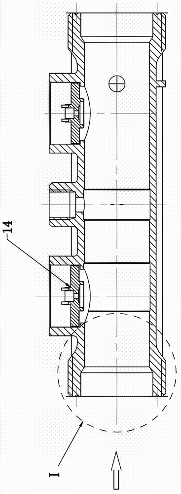
The existing ultrasonic heat meter steady flow device, such as figure 1 As shown, the shape of the inner cavity of the water inlet part I on the meter body is approximately straight cylindrical, and the unsteady water flow flows into the meter body from the water inlet part I. The flow velocity is not yet stable, and even the water flow still has a vortex. The measurement area of ​​the ultrasonic transducer 14 in the heat meter causes the ultrasonic measurement flow rate to be inaccurate, which in turn affects the accuracy of the heat meter measurement

Method used


Image

  • Current stabilizer for ultrasonic heat meter
  • Current stabilizer for ultrasonic heat meter
  • Current stabilizer for ultrasonic heat meter

Examples


Embodiment 1

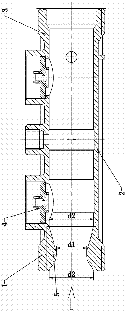
[0015] Such as figure 2 As shown, the ultrasonic heat meter flow stabilization device of the present invention includes a water inlet 1 at the left end, a middle part 2 and a water outlet 3 at the right end. The water inlet 1, the middle part 2 and the water outlet 3 are integrally formed and are all made of stainless steel. material, the shape of the inner cavity of the middle part 2 is a straight cylinder, the ultrasonic transducer 4 is installed at the connection position between the middle part 2 and the water inlet part 1 and the water outlet part 3, and the inner cavity of the water inlet part 1 is installed with Annular protrusion 5 with a smooth surface (that is, the annular protrusion 5 and the water inlet 1 are a split structure, which is convenient for installation and disassembly, or replacement of annular protrusions 5 with different inner diameters and shapes). The setting of the annular protrusion 5 makes the inner cavity of the water inlet 1 The shape is an ho...

Embodiment 2

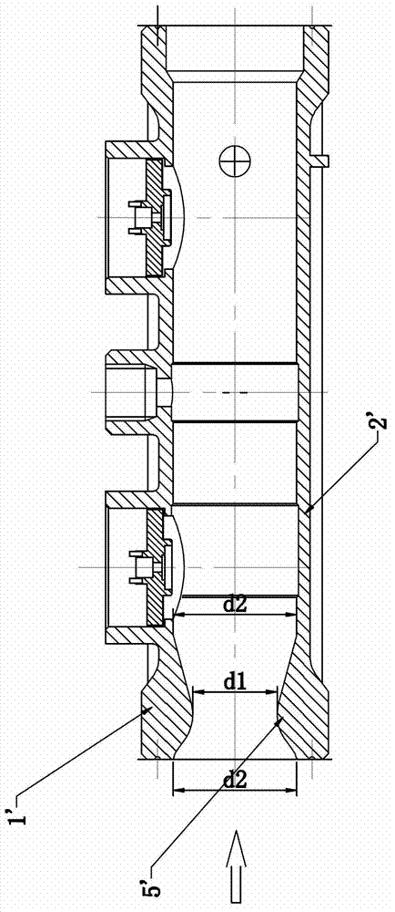
[0017] Compared with the first embodiment, this embodiment is only different in that: the annular protrusion 5' is integrally formed with the water inlet part 1'.

[0018] Such as figure 2 , image 3 As shown, the embodiment of the present invention when applied in the small watch body is: wherein the minimum diameter d1 of the inner cavity of the water inlet part 1, 1' is 15mm, and the maximum diameter d2 of the inner cavity of the water inlet part 1, 1' is 22mm, The lumen diameter of the middle part 2, 2' is 22mm.


PUM

PropertyMeasurementUnit
Minimum diameteraaaaaaaaaa
The maximum diameteraaaaaaaaaa
Lumen diameteraaaaaaaaaa

Abstract

The invention relates to an ultrasonic heat meter used for measuring water flow speed and flow in a heating system, in particular to a current stabilizer for the ultrasonic heat meter. The current stabilizer is simple in structure, good in current stabilizing effect and accurate in ultrasonic measuring results and comprises a water inlet portion positioned at a left end, a middle portion and a water outlet portion positioned at a right end, an inner cavity of the middle portion is in a straight shape, ultrasonic transducers are mounted at connection positions between the middle portion and the water inlet portion and the water outlet portion, an inner cavity of the water inlet portion is provided with annular protrusions with smooth surfaces, the arrangement of the annular protrusions enables the inner cavity of the water inlet portion to be in an hourglass shape with the longitudinal section area gradually reduced first and then slowly increased, and smooth transition is realized at the connection position of the inner cavity of the water inlet portion and the inner cavity of the middle portion.

Description

technical field [0001] The invention relates to an ultrasonic heat meter used for measuring the water flow velocity and flow rate in a heating system, in particular to a flow stabilizing device of the ultrasonic heat meter. Background technique [0002] The ultrasonic heat meter is a relatively advanced heat meter in the existing technology. Specifically, it uses ultrasonic waves to measure the flow rate and flow rate of the water entering the meter body between the water inlet and the water outlet in the heating system, and then measures the heating water consumption of the user. and billing. The existing ultrasonic heat meter steady flow device, such as figure 1 As shown, the shape of the inner cavity of the water inlet part I on the meter body is approximately straight cylindrical, and the unsteady water flow flows into the meter body from the water inlet part I. The flow velocity is not yet stable, and even the water flow still has a vortex. The measurement area of ​​t...

Claims


Application Information

Patent Timeline
IPC IPC(8): G01K17/06G01F1/66G01P1/00
Inventor 于大永陈卫鹏
Owner RUINA INTELLIGENT EQUIP CO LTD
Learn More