
Pneumatic self-locking valve

A pneumatic, self-locking valve technology, applied in valve details, valve devices, engine components, etc., can solve problems such as inability to work for a long time, poor compatibility with corrosive working media, etc., to avoid contact and solve long-term and Compatibility problems with corrosive working medium, small volume effect

Inactive Publication Date: 2012-12-19
SHANGHAI INST OF SPACE PROPULSION
View PDF7 Cites 7 Cited by
  • Summary
  • Abstract
  • Description
  • Claims
  • Application Information

AI Technical Summary

Problems solved by technology

[0005] The technical problem to be solved by the present invention is to provide a pneumatic self-locking valve with a new structure, which aims to overcome that the existing pneumatic dynamic sealing form usually adopts rubber O-ring seal, which has poor compatibility with corrosive working medium and cannot Defects of long-term work, while achieving large flow, light weight and long-term work under corrosive working media

Method used


Image

  • Pneumatic self-locking valve
  • Pneumatic self-locking valve
  • Pneumatic self-locking valve

Examples


Embodiment Construction

[0018] The present invention will be further elaborated below in conjunction with the accompanying drawings and specific embodiments. These examples should be understood as only for illustrating the present invention but not for limiting the protection scope of the present invention. After reading the contents of the present invention, those skilled in the art can make various changes or modifications to the present invention, and these equivalent changes and modifications also fall within the scope defined by the claims of the present invention.

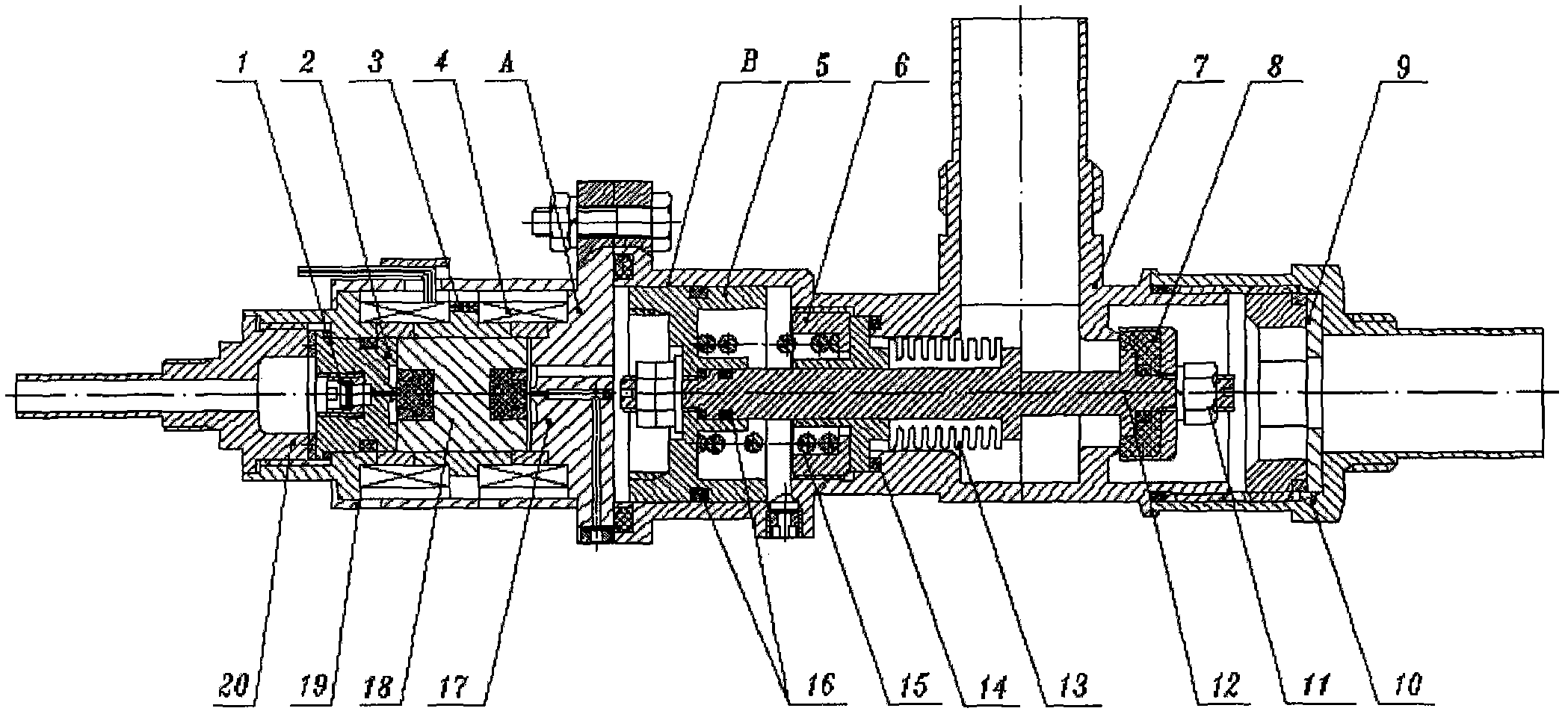
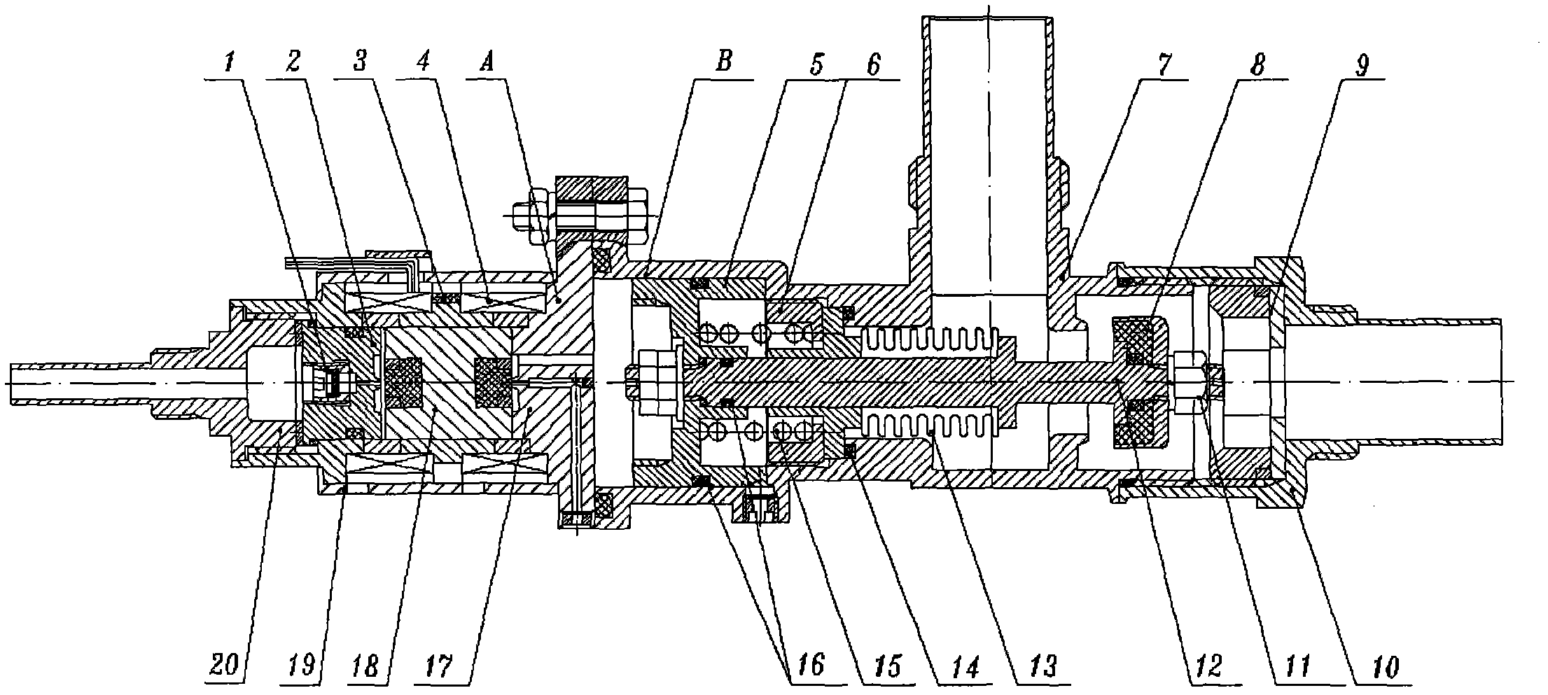
[0019] Such as figure 1 As shown, the pneumatic self-locking valve provided by the preferred embodiment of the present invention is mainly composed of a filter 1, a first suction valve seat 2, a locking magnetic ring 3, a coil assembly 4, a piston 5, a compression nut 6, a housing 7. Plastic valve core 8, adjusting orifice plate assembly 9, imported welding nozzle 10, lock nut 11, piston shaft assembly 12, metal bellows 13, sealing...


PUM


Abstract

The invention discloses a pneumatic self-locking valve. The self-locking valve is formed by a self-locking pilot valve and a pneumatic main valve via a coupling flange, wherein the self-locking pilot valve comprises a filter, a first pull-in valve seat, a lockup magnet ring, coil assemblies, a second pull-in valve seat, a valve plug and a housing; the filter is installed at the inlet of the first pull-in valve seat; the first pull-in valve seat, the valve plug and the second pull-in valve seat are made of magnetic conductance material, are installed in the coil assemblies and are sealed by permanent magnet suction of the lockup magnet ring; the housing is sleeved on the coil assemblies; the pneumatic main valve comprises a piston, a compression nut, a shell, a plastic valve plug, a lockup nut, a piston shaft assembly, metal bellows and return springs; the piston shaft assembly and the metal bellows are installed in the shell; the lockup nut locks and installs the plastic valve plug on the piston shaft assembly; the compression nut fixes the piston shaft assembly on the shell; and the installation positions of the return springs are used for piston return. The self-locking valve is suitable for circulation management of working media of spacecraft propulsion systems.

Description

technical field [0001] The invention relates to a fluid control element, in particular to a pneumatic self-locking valve which is especially suitable for strong corrosive working medium. Background technique [0002] As a working medium circulation management device of the spacecraft propulsion system, the self-locking valve can keep the valve open or closed through pulse signals without the need for long-term voltage energy provided by the power supply. At present, the known self-locking valve structure is generally a direct-acting type, which directly controls the opening and closing of the valve core through the suction force generated by the electromagnet, and realizes the function of controlling the flow or cut-off of the working medium. [0003] The flow rate applicability of the existing direct-acting self-locking valve is small, because the large-diameter direct-acting self-locking valve requires a large electromagnetic suction force, resulting in a corresponding inc...

Claims


Application Information

Patent Timeline
Patent Type & Authority Applications(China)
IPC IPC(8): F16K31/122F16K31/06F16K41/00
Inventor 潘振兴魏青
Owner SHANGHAI INST OF SPACE PROPULSION
Learn More